鑫景福致力于滿足“快速服務,零缺陷,輔助研發”PCBA訂購單需求。


PCBA加工
PCB copy board negative film correction and terminal block
Five ways to correct negative sentences reproduction of printed circuit board
In the process of PCB reproduction, the negative film often deforms, whICh is usually caused by improper temperature and humidity control or overheating of the exposure machine, which will affect the quality and efficiency of PCB reproduction. The method to deform the negative.
1. Splicing method
It is applicable to films with less dense packaging and inconsistent deformation of each film. The utility model is particularly effective for the correction of the solder mask and the power mask of the multilayer plate.
Specific operation: cut the deformed part of the negative film, re splice the hole bits of the test drilling plate, and then copy. Of course, this applies to SIMple deformed lines, large line width and spacing, and irregular deformed figures; It is not applicable to films with high linear density, line width and spacing less than 0.2mm.
Tips: When splicing, pay attention to damage the wire as little as possible, and do not damage the pad. When modifying versions after splicing and copying, pay attention to the correctness of the connection relationship.
2. Change the hole bit method
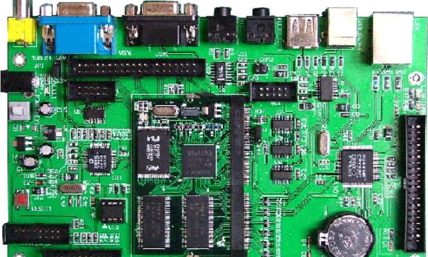
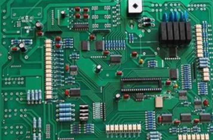
Circuit board

It is suitable for correcting films with dense lines or uniform deformation of each film layer.
Specific operation: First, compare the negative film and the drilling test plate, measure and record the length and width of the drilling test plate respectively, and then adjust the hole position on the digital programmer according to the two deformations of the length and width., The adjusted drill test plate will adapt to the deformed film. The advantage of this method is that it eliminates the trouble of editing the negative and ensures the integrity and accuracy of the graphics. The disadvantage is that the correction of negative film with very serious local deformation and uneven deformation is invalid.
Tips: To use this method, you must first master the operation of digital programming instruments. After lengthening or shortening the hole position with the programming instrument, the out of tolerance hole position shall be reset to ensure the accuracy.
3. Printed circuit board gasket overlapping method
It is applicable to films with line width and spacing greater than 0.30mm and less dense pattern lines.
Specific operation: Enlarge the hole on the test board into a pad to make the circuit chips overlap and deform, so as to ensure the technical requirements for the minimum ring width.
Tips: After overlapping and copying, the pad will be oval. After overlapping and copying, the edges of lines and disks will appear halo and deformation. If users have very strict requirements on the appearance of PCB, please use it with caution.
4. Photographic method
Only applicable to silver salt film. This tool can be used when it is not convenient to re drill the test plate and the film has the same deformation rate in the length and width directions. The operation is also simple: just use the CAMera to zoom in or out of the deformed figure.
Tips: Generally, film loss is large, and it requires multiple debugging to get a satisfactory circuit diagram. When taking photos, the focal length should be accurate to prevent line deformation.
5. Suspension method
It is applicable to the undistorted negative film and can also prevent the negative film from deforming after copying.
Specific operation: Before copying, take the film out of the seaLED bag and hang it in the working environment for 4-8 hours to make the film deformed before copying. After copying, the probability of deformation is very SMAll. Other measures shall be taken for the deformed film.
Tips: Since the film will change with the change of ambient temperature and humidity, please ensure that the humidity and temperature at the film hanging place are the same as those at the workplace, and that the film is kept in a ventilated and dark environment to prevent the film from being polluted.
Of course, the above are the remedial measures after the film deformation. The engineer should still consciously prevent film deformation. During the reproduction of printed circuit board, the temperature is usually strictly controlled at 22 ± 2 ° C and the humidity is 55% ± 5% RH. Use a cold light source or an aerator with a cooling device, and constantly replace the spare film.
Class IV printed circuit board terminals
PCB terminals are mainly divided into four categories: pluggable terminal blocks, screw terminal blocks, spring terminal blocks and barrier terminal blocks.
Category I: pluggable patch panel
The pin spacing of the product is 3.5, 3.81, 5.0, 5.08, 7.5 and 7.62, and the number of poles is 2-24. It can provide a screw fixed socket for matching and anti vibration connection. The plug adopts side connection technology, that is, the direction of the screw is perpendicular to the direction of the wire.
Type II: screw terminals
The circuit board terminal has always occupied a very important position in the electronic industry, and now it has become an important part of the printed circuit board. Its structure and design are more solid, with the characteristics of convenient wiring and reliable threaded connection; Compact structure, reliable connection, with its own advantages; The lifting principle of clamp body ensures reliable wiring and large wiring capacity; The welding leg and clamp wire divide the main body into two parts to ensure that the distance when tightening the screw will not be transferred to the welding spot and damage the welding spot; The shell is firm and reliable, and the needle pitch is accurate.
Category 3: Spring type printed circuit board terminals
The equal spacing of spring loaded PCB terminals is 2.54mm, 3.50mm, 5.00mm, 7.50mm, 7.62mm; The single core conductor can be directly inserted without the help of the handle, but the smaller conductor can be opened and clamped by the handle clamp; There is no button specification, and the height can be greatly reduced. When taking up the wire, press it down with a screwdriver to take it out easily; Most spring type terminals are assembled piece by piece; This wiring method is very suitable for communication system, lighting system, monitoring system and building wiring; Various wiring directions are easy to assemble in a small space, can be combined with any number of contacts, easy to operate, and suitable for high-density wiring needs.
Category IV: Obstacle PCB wiring board
The fence type code is LW; The middle pin bit code is C; Side needle position code is B; The fixed location code is M; The code of the looper model is R; The lead bonding code is Q; LW fence type products have simple structure, plate type, and intuitive and firm crimping method; Diameter range of steel wire: 0.5m-6m.


抖音二維碼

Q Q二維碼

微信二維碼
點擊
然后
聯系
然后
聯系
電話熱線
13410863085Q Q

微信

- 郵箱