鑫景福致力于滿足“快速服務(wù),零缺陷,輔助研發(fā)”PCBA訂購(gòu)單需求。


PCBA方案設(shè)計(jì)

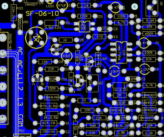
PCB layout technology for optimizing power module effICiency
Starting from power supply layout, this paper introduces PCB layout methods, examples and technologies of optimizing power module efficiency When planning the power supply layout, the first consideration is the physical loop area of the two switching current loops Although these loop areas are almost invisible in the power module, it is still important to understand their respective current paths when two loops extend beyond the module The current self conducting input bypass capacitor (Cin1) passes through the high side MOSFET during the continuous on time of the MOSFET, reaches the internal inductor and the output bypass capacitor (CO1), and returns to the input bypass capacitor (CO1) It is formed during the closing time of the internal high side MOSFET and the opening time of the low side MOSFET The energy stored in the internal inductor flows back to GND through the output bypass capacitor and the low side MOSFET The region where the two loops do not overlap each other (including the boundary between the loops) is the high di/dt current region The input bypass capacitor (Cin1) plays a key role in supplying high frequency current to the converter and returning it to its source path. The output bypass capacitor (Co1) does not carry as much AC current, but it can be used as a high-frequency filter for switching noise For the above reasons, the input and output capacitors should be as close as possible to the respective VIN and VOUT pins on the module As shown in Figure 2, the inductance of these connections can be minimized by keeping the trace between the bypass capacitor and its respective VIN and VOUT pins as short and wide as possible
PCB board

Reducing the inductance PCB layout in the transformer has two main advantages Improve equipment efficiency by promoting energy transfer between Cin1 and CO1 This will ensure that the module has a good high-frequency bypass and reduce the induced voltage peak/dt current caused by high voltage It can also reduce equipment noise and voltage stress to ensure normal operation Second, reduce electromagnetic interference Connecting capacitors with SMAll parasitic inductance will show low impedance to high frequency, thus reducing conducted radiation Ceramic capacitors (X7R or X5R) or other low ESR type capacitors are recommended. Only when the additional capacitors are close to the GND and VIN terminals will it work to add more input capacitors The unique design of the power module inherently has low radiation and conducted EMI, and following the PCB layout guidelines presented in this paper will produce higher efficiency The path planning of loop current is often ignored, but it plays a key role in optimizing power supply design In addition, the grounding tracks of Cin1 and CO1 should be shortened and widened as far as possible, and directly connected to the exposed bonding pad, which is especially important for the input capacitor (Cin1) ground connection with high AC current Ground pins (including exposed pads), input and output capacitors, soft start capacitors, and reverberation resistors in modules should all be connected to the return layer on the PCB This return layer can be used as a return path for very low inductance currents and also as a heat sink discussed below The feedback resistor should also be placed as close as possible to the FB (feedback) pin of the module. To minimize the potential noise selection at this high impedance node, it is important to keep the trace between the FB pin and the center tap of the reverberation resistor as short as possible The available compensation elements or feedforward capacitors should be as close to the upper reverberation resistor as possible
Thermal Design Recommendations
While the compact layout of the module provides electrical benefits, which has a negative impact on thermal design and dissipates equivalent power from a small space With this in mind, a large exposed pad is designed on the back of the power module package and electrically grounded This pad helps provide very low thermal impedance from the internal MOSFET (which usually generates most of the heat) to the PCB. The thermal impedance (??JC) from the semiconductor junction to the outer package of these devices is 1.9°C/W. It is ideal to reach the JC value of the industry! The heat * cannot be dispersed on the exposed pad So, what determines the CA value? The thermal resistance from the exposed pad to the air is completely controlLED by the PCB design and the related radiator Now we can quickly understand how to carry out SIMple PCB thermal design without heat sink, because the thermal impedance between the junction and the top of the outer package is relatively high compared with the thermal impedance from the junction to the wafer pad. In this estimate from When considering the thermal impedance (JT) from the junction to the surrounding air, we can ignore the JA cooling path The first step in thermal design is to determine the power to dissipate The power dissipated by the module (PD) can be easily calculated using the efficiency graph (?·) published in the datasheet. Then, we use the two designed temperature constraints, TAmbient and rated junction temperature, TJunction (125 ° C), to determine the thermal resistance required for modules packaged on PCB We use a simplified approximation of convective heat transfer from the surface of a PCB (with undamaged one-ounce copper heat sinks and numerous thermal vias on both the top and bottom layers) to determine the board area required for heat dissipation. The required PCB area approximation does not take into account the role of thermal vias that transfer heat from the top metal layer (where the package is connected to the PCB) to the bottom metal layer. The bottom layer acts as the second surface layer, and convection can transfer heat from the plate Use at least 8-10 hot vias for valid board area approximations The thermal resistance of the hot through-hole is approximated by the following equation This approximation applies to a typical through-hole. 5 oz copper sidewall with a diameter of 12 mils and 0 Design as many cooling holes as possible in the whole area under the exposed gasket, and make these holes form an array with a spacing of 1:1. 5mm The power module provides an alternative/DC converter for complex power design and typical DC related PCB layout Although the layout challenge has been eliminated, some engineering work still needs to be done to optimize the module efficiency PCB design with good bypass and thermal stability


抖音二維碼

Q Q二維碼

微信二維碼
點(diǎn)擊
然后
聯(lián)系
然后
聯(lián)系
電話熱線
13410863085Q Q

微信

- 郵箱