鑫景福致力于滿足“快速服務,零缺陷,輔助研發”PCBA訂購單需求。


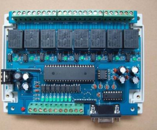
PCBA方案設計
Radio frequency is the definition of electromagnetIC wave according to its application, specifically referring to the electromagnetic wave with a certain wavelength that can be used for radio communication. The definition of frequency range is confusing. There are 30MHz to 3GHz and 300MHz to 40GHz in the data, overlapping with microwave; Another definition based on spectrum refers to the electromagnetic wave whose wavelength ranges from 1 m to 1 m, and its corresponding frequency ranges from 30 Hz to 300 MHz; The frequency boundary between radio frequency (RF) and microwave is relatively vague, and changes with the progress of device technology and design methods.
Considering the particularity, the circuit model of PCB upload transmission line is mainly considered. Since the transmission line adopts lumped parameter circuit model and distributed parameter circuit model, the dividing line can be considered as l/ λ ≥ 0.05. (where l is the geometric length; λ Is the working wavelength) The radio frequency link defined in this specification refers to the analog signal circuit whose transmission line structure adopts distributed parameter model. The PCB line length rarely exceeds 50cm, so the minimum consideration is 30MHz analog signal; Since more than 3G is usually considered as pure microwave, it can be considered to stop there; Considering that the distance between process elements can reach 0.5mm, the highest frequency can also be set at 30GHz, which is of little significance.
To sum up, it can be considered that RF PCB can be defined as a PCB with analog signals in the frequency range of 30MHz to 6GHz, but whether the lumped or distributed parameter model is used can be determined according to the formula.
Because the dielectric constant of the substrate is relatively high and the propagation speed of electromagnetic wave is relatively slow, the wavelength is shorter than that in the air. According to the microwave principle, the requirements of the microstrip line on the dielectric substrate are: the dielectric loss is SMAll, the dielectric constant should be constant within the required frequency and temperature range, the thermal conductivity and surface finish should be high, and the conductor should have good adhesion. Requirements for metal materials constituting the conductor strip: high conductivity, small resistance temperature coefficient, good adhesion to the substrate, easy welding, etc.
In addition to the general principle of considering the current size, the printed wire on the RF Circuit PCB must also consider the characteristic impedance of the printed wire, and the impedance matching must be strictly carried out. The impedance control of the printed wire must be considered when making the PCB. The characteristic impedance of printed wire is related to the material characteristics and physical parameters of PCB, so PCB design engineers must be clear about the performance of pcb board.
The thickness of the RF printed circuit board PCB is usually an integral multiple of 0.2mm, such as 0.8mm, 1.0mm, 1.6mm, etc. SometiMES the thickness of the printed circuit board is expressed in inches. The specific thickness shall be subject to the result calculated by impedance control.
Pad surface treatment
Generally, there are the following types:
1) Generally, the tin lead alloy HASL process is adopted, and the tin layer surface should be flat without exposed copper. It is only necessary to ensure good weldability within 6 months. In order to obtain better skin effect, electroless gold plating process or OSP process can be selected for RF board. At the same time, it helps to reduce environmental pollution.
2) If there are devices with fine spacing on the PCB (such as BGA with spacing of 0.5mm), or the plate thickness is ≤ 0.8mm, chEMIcal (non electric) nickel gold (Ep. Ni2. Au0.05) can be considered. There is also an organic coating process (OSP for short), which is not suitable for the time being due to the problems of short solderability period, tackiness and non resistance to soldering.
3) For boards with bare chips (requiring hot pressing or ultrasonic welding, commonly known as Bonding) or buttons (such as mobile phone boards), electroless nickel and gold plating processes (Et. Ni5. Au0.1) must be used. Some manufacturers also adopt the whole plate gold plating process (Ep. Ni5. Au0.05). The former has more flat surface, more uniform coating thickness and more welding resistance, while the latter is cheap and has good brightness.
In terms of cost, the electroless nickel and gold plating process (Et. Ni5. Au0.1) is more expensive than tin spraying, while the whole plate gold plating process is cheaper than tin spraying
4) The printed plug is generally plated with hard gold, that is, a gold alloy with purity of 99.5% - 99.7% containing nickel and cobalt. The general thickness is 0.5~0.7 μ m. MARKed as: Ep. Ni5. Au0.5
The coating thickness is determined according to the number of times of insertion and removal, generally 0.5 μ M thickness can withstand 500 times of plugging, 1 μ M thickness can withstand 1000 times of plugging.
The precision of the characteristic impedance must be strictly controlLED in the processing and manufacturing of RF circuit boards, and the precision of the dielectric constant is closely related to the uniformity of the resin content of the substrate material (prepreg). The technical indicators of resin content in the prepreg are formulated by each PCB substrate material manufacturer according to the different actual forming and processing processes of the PCB manufacturer and the capacity of the production level. Due to the different resin content, there are differences in the melt viscosity of the prepreg and in the laminating process. These will lead to differences in PCB insulation layer thickness and accuracy. multilayer boards made of prepreg materials from different manufacturers with different resin content indexes show different levels and accuracy in their dielectric properties, especially dielectric constant values. Therefore, to improve the high-precision control of PCB characteristics, substrate material manufacturers must cooperate well with PCB manufacturers in terms of the index control of resin content in the production of prepreg. See Appendix C.
Due to the special packaging of RF components, when selecting newly packaged RF components or compatible components, developers must fully communicate with technologists in the early stage to ensure the manufacturability of components.
Special attention shall be paid to the coating thickness and material of the welding end of RF components to avoid empty welding and cold welding (especially for ceramIC components with silver plated welding end) in the production process.
The flatness of RF components should be less than 0.005 ", especially ceramic modules, such as VCO, power amplifier and filter.
Special attention shall be paid to the tolerance value of electrical performance of RF passive components. The existing tests show that if the component tolerance value exceeds 5% or more, the distribution value in the circuit is diversified. Therefore, attention should be paid to the early selection in order to obtain good electrical performance optimization.
Requirements for RF connectors: it is recommended that the thickness of the coating on the surface of the connector and PCB center contact pin and digital signal terminal pin be 30-50 μ inch gold, with an inner layer thickness of 50-150 μ Inch Ni; The contact part between SMT connector and PCB pad shall be controlled within+0, -0.002 ".
Keep the digital circuit away from the analog circuit as far as possible; Ensure that the ground below the RF cable is solid and large, and try to lay the RF cable on the surface.
Digital and analog signal lines shall not be routed across the area. If RF cabling must pass through the signal line, it is preferable to lay a layer of ground connected to the main ground along the RF cabling between them; The secondary selection ensures that the RF line and the signal line cross each other to minimize capacitive coupling. At the same time, more ground shall be laid around each RF line as much as possible and connected to the main ground. In general, RF printed PCB wires should not be wired in parallel and should not be too long. If parallel wiring is really required, a ground wire should be added between the two wires (the ground wire should be punched to ensure good grounding). RF differential line, parallel line, two parallel lines with ground wire outside (ground wire is punched to ensure good grounding), and the characteristic impedance of the printed wire is designed according to the requirements of PCB devices.


抖音二維碼

Q Q二維碼

微信二維碼
點擊
然后
聯系
然后
聯系
電話熱線
13410863085Q Q

微信

- 郵箱