鑫景福致力于滿足“快速服務,零缺陷,輔助研發”PCBA訂購單需求。


PCBA方案設計

I will take an actual hardware design project as an example to discuss with you the basIC principles and ideas of hardware development, and welcome you to actively put forward your own questions and views.
Fully understand the design requirements of all parties and determine the appropriate solution
To start a hardware development project, the original driving force will come from many aspects, such as the needs of the MARKet, based on the needs of the entire system architecture, the needs of PCB application software department to achieve functions, and the needs to improve the ability of a certain aspect of the system. Therefore, as a hardware system designer, you should take the initiative to understand the needs of all aspects, and put forward the most appropriate hardware solutions. For example, the original driving force of Project A CAMe from a high-level software team within the company. In practice, they found that the IP forwarding capability of the original processor board could not meet the requirements, which would cause great inconvenience to the configuration and use of the system, so they put forward the requirements for new hardware. According to this goal, two high-performance network processors are targeted in the hardware scheme, and then in-depth communication with the software designer is required to determine the memory size, internal structure, number and type of external interfaces and debugging interfaces and other details. For example, software personnel like to completely separate the control signaling path and data path, so they should carefully consider when determining the direction of internal data. At the beginning of the project, a lot of discussion meetings need to be held. All relevant departments should be invited as much as possible to participate. There are three advantages. First, we can fully understand everyone's needs to avoid missing important functions in the system design. Second, we can let all departments know about the project and make preparations for cooperation in terms of time and personnel in advance. Third, from the emotional perspective, all departments have participated in the design at the beginning, This project has become a common crystallization of our efforts, which will be cared for and well cooperated by all of us, and will be very helpful to the completion of the work.
Problems needing attention in schematIC design
There should be a "take principle" in schematic design, and current chip manufacturers can generally provide schematic diagrams of reference design, so try to use these resources to make some play on the basis of fully understanding the reference design. When the main chip is selected, the most critical peripheral design includes power supply, clock and interconnection between chips.
The power supply is the basis to ensure the normal operation of the hardware system. The detaiLED analysis shall be made in the design: the power input that the system can provide; Power output required by the board; Current required for each power supply; Power circuit efficiency; Allowable fluctuation range of each power supply; Power on sequence required by the whole power system, etc. For example, the network processor in project A needs 1.25V as the core voltage, with an accuracy of+5% - - 3%, and a current of about 12A. According to these requirements, 5V power input is used in the design, and a suitable power supply circuit is built using Linear's switching power controller and IR's MOSFET. The accuracy requirements determine the ESR selection of the output capacitor, and to prevent voltage drop caused by excessive current, The remote feedback function is added.
The realization of the clock circuit should take into account the jitter and other requirements of the target circuit. Project A used GE PHY devices. At the beginning, a zero delay clock distribution chip with an internal phase-locked loop was used to provide a 100MHz clock. As a result, packet loss occurred on the GE link. Later, a SIMple clock buffer device was used to solve the packet loss problem. It is analyzed that the internal phase-locked loop introduced jitter.
The interconnection between chips should ensure the error free transmission of data. In this regard, high-speed differential signal lines have the characteristics of high speed, good wiring, and good signal integrity. The interconnection between multiple chips in Project A uses high-speed differential signal lines, which have no problems in debugging and testing.
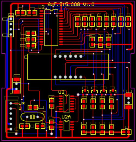
3 Problems needing attention in PCB design
In order to achieve a clear purpose, the important signal lines should be very strict with the length of the wiring and the processing of the ground loop, while the low-speed and unimportant signal lines can be placed on a lower priority of the wiring. Important parts include: division of power supply; Length requirements for clock line, control line and data line of memory; High speed differential wiring, etc.
In Project A, a 1G DDR memory is implemented using memory chips. The wiring of this part is very critical. In consideration of the topology distribution of control lines and address lines, the length difference control of data lines and clock lines, and other aspects, specific wiring rules can be obtained according to the chip's data manual and the actual working frequency during the implementation process. For example, the length difference of data lines in the same group cannot exceed how many mils, The length difference between each path cannot exceed many mils, etc. When these requirements are determined, PCB designers can be explicitly required to implement them. If all the important wiring requirements in the design are clear, they can be converted into overall wiring constraints, and PCB design can be realized by using the automatic wiring tool software in CAD, which is also a development trend in China.
High Speed PCB design
4 Inspection and commissioning
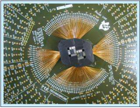
When you are ready to debug a board, you must carefully make a visual inspection to check whether there is a visible short circuit, soldering of pins and other faults during the welding process, check whether there are problems such as wrong placement of component models, wrong placement of the first leg, missing assembly, etc., and then use a multimeter to measure the resistance of each power supply to the ground to check whether there is a short circuit. This good habit can avoid damaging the single board after power on rashly. In the process of debugging, we should have a peaceful mind. It is very normal to encounter problems. What we need to do is to make more comparisons and analyses, gradually eliminate the possible causes, and firmly believe that "everything can be solved" and "there must be a reason for problems". In this way, we will succeed in debugging.
5. Some concluding remarks
Now, from a technical point of view, every design can finally be done, but the success of a project depends not only on the realization of PCB technology, but also on the completion time, product quality, and team cooperation. Therefore, good team cooperation, transparent and frank project communication, meticulous and thorough research and development arrangements, and abundant materials and personnel arrangements can ensure the success of a project.
A good hardware engineer is actually a project manager. He/she needs to obtain the requirements for his/her design from external communication, and then summarize and analyze them into specific hardware implementations. He/she should also contact many chip and solution suppliers to select appropriate solutions. When the schematic diagram is completed, he/she should organize colleagues to cooperate in the review and inspection, and also work with CAD engineers to complete the PCB design. At the same time, prepare the BOM list, start purchasing and preparing materials, and contact the processing manufacturer to complete the installation of plates. In the process of debugging, he/she should organize software engineers to tackle key problems and debug together, cooperate with test engineers to solve problems found in the test, and when the product is launched to the site, timely support should be provided if problems occur. Therefore, as a hardware designer, it is necessary to exercise good communication skills, the ability to adjust to pressure, the ability to coordinate and make decisions to deal with multiple affairs at the same time, and a good peace of mind.
Also careful and careful, because a minor oversight in the hardware design often results in very large economic losses. For example, in the past, a board was misoperated when the PCB design was completed and the manufacturing documents were produced, causing the power supply layer and the stratum to be connected. After the PCB was manufactured, there was no inspection and direct online mounting. The short circuit problem was found only when the test was completed.


抖音二維碼

Q Q二維碼

微信二維碼
點擊
然后
聯系
然后
聯系
電話熱線
13410863085Q Q

微信

- 郵箱