鑫景福致力于滿足“快速服務,零缺陷,輔助研發”PCBA訂購單需求。


行業新聞
Partition design of mixed signal PCB
The design of mixed signal PCB board is very complex, and the layout and wiring of components, as well as the processing of power and ground, will directly affect the circuit effICiency and electromagnetic compatibility efficiency The grounding and power zoning design described in this paper can optimize the performance of mixed signal circuits How to reduce the mutual interference between digital signals and analog signals? Two basic principles of electromagnetic compatibility (EMC) must be understood before design: the first principle is to minimize the area of the current loop; The second principle is that the system uses only one reference surface. Tablet computer, which can form DIPole antenna (Note: the radiation size of SMAll dipole antenna is proportional to the length and frequency of wire); If the signal cannot pass as far as possible when the small loop returns, a large loop antenna can be formed (note: the radiation size of the small loop antenna is proportional to the loop area and frequency square). These two situations should be avoided as far as possible in the design It is recommended to separate digital and analog grounding on the mixed signal circuit board, so as to achieve isolation between digital and analog grounding Although this method is feasible, there are many potential problems, especially in complex large-scale systems The key problem is that the wiring cannot pass through the split gap Once the wiring is crossed, electromagnetic radiation and signal crosstalk will increase sharply The common problem in PCB design is that the signal wire passes through the split grounding or power supply to generate electromagnetic interference problems
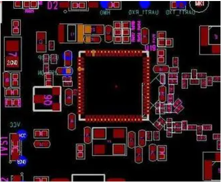
PCB board

We use the above segmentation method. The signal line crosses the gap between two grounding wires. What is the return path of the signal current? It is assumed that two separate grounds are connected together at some place (usually a single point connection at some place), in this case, the ground current will form a large loop. The high-frequency current flowing through the large loop will generate radiation and high grounding inductance. If the low level analog current flowing through the large loop is easy to be interfered by external signals. Unfortunately, when the split grounding is connected together at the power supply, a very large current loop will be formed. In addition, analog and digital are connected together through long wires to form a dipole antenna. Understanding the location and pipeline of the current returning to the ground is the key to optimize the design of the mixed signal board. Many design engineers only consider the flow direction of the signal current, ignoring the specific path of the current. If the ground plane must be divided and the wiring must pass through the gap between partitions, a single point connection can be made between the divided grounding to form a connection bridge between the two grounding, and then the wiring can be made through the connection bridge. In this way, a DC return path can be provided under each signal line, thus forming a small loop area. Optical isolators or transformers can also be used to achieve signals across split gaps. For the former, light signals pass through the gap; In the case of transformers, the magnetic field passes through the dividing gap. Another possible approach is to use differential signals: signals flow from one line and return from the other, in which case grounding is not required as a return path. In order to deeply study the interference of digital signals to analog signals, we must first understand the characteristics of high-frequency current. High frequency current always selects impedance (inductance), that is, the path directly below the signal. This return current flows through the adjacent circuit layer, whether it is the power layer or the ground layer.
In practice, unified grounding is usually preferred, and PCB board is divided into analog part and digital part. The analog signal is wired in the analog area of all layers of the circuit board, while the digital signal is wired in the digital circuit area. In this case, the digital signal loop current will not flow into the analog signal ground. Only when the digital signal is routed to the analog part of the circuit board, or the analog signal is routed to the digital part of the circuit board, can digital analog interference occur. The problem is not that there is no split grounding, but that the digital signal is improperly wired. pcb board design adopts unified grounding. Through the division of digital circuit and analog circuit and proper signal wiring, some difficult layout and wiring problems can usually be solved without causing some potential faults caused by grounding separation. In this case, the layout and partition of components become the key to determine the design quality. If the layout is correct, the digital ground current will be limited to the digital part of the circuit board and will not interfere with the analog signal. Such wiring must be carefully checked to ensure full compliance with the wiring rules. Otherwise, improperly wired signal wires may completely damage the original very good circuit board. When the analog and digital grounding pins of the A/D converter are connected together, most A/D converter manufacturers recommend that AGND and DGND pins be connected to the same low impedance ground through short leads. (Note: Since most A/D converter chips do not connect analog ground and digital ground together, analog ground and digital ground must be connected through external pins), any external impedance connected to DGND will pass through parasitic capacitance. More digital noise is coupLED to analog circuits inside integrated circuits. According to this suggestion, both AGND and DGND pins of A/D converter need to be connected to analog ground, but this method will cause problems, such as whether the ground of digital signal decoupling capacitor should be connected to analog ground or digital ground. If the system has only one A/D converter, the above problems can be easily solved. As shown in Figure 3 above, separate the grounding under the A/D converter and connect the analog grounding and digital grounding together. When using this method, it must be ensured that the width of the connection bridge between the two grounding wires is the same as that of the integrated circuit, and no signal wire can pass through the division gap. For example, if there are multiple A/D converters in the system, how do I connect 10 A/D converters? If analog ground and digital ground are connected together under each A/D converter, there will be multipoint connection, and the isolation between analog ground and digital ground will be meaningless. If you do not connect in this way, you are violating the manufacturer's requirements. The solution starts with a unified foundation. As shown in Figure 4 below, the unified grounding is divided into analog part and digital part. This layout and wiring not only meet the requirements of integrated circuit device manufacturers for low impedance connection of analog grounding and digital grounding pins, but also will not form a loop antenna or dipole antenna, thus causing electromagnetic compatibility problems.
If you have questions about the unified grounding method of mixed signal PCB design, you can use the method of dividing the ground plane to layout and route the entire circuit board. When designing, pay attention to making the circuit board easy to use in subsequent experiments. Jumpers less than 1/2 inch apart or 0 ohm resistors connect the split ground together. Pay attention to zoning and wiring, and ensure that there is no digital signal line at the top of the analog part, and there is no analog signal line at the top of the digital part on all layers. In addition, no signal line can cross the ground gap or divide the gap between power supplies. To test the function and EMC performance of the circuit board, connect the two grounds together through a 0 ohm resistor or jumper, and retest the function and EMC performance of the circuit board. The comparative test results show that in almost all cases, the unified solution is superior to the segmented solution in terms of function and EMC performance. Is the method of land division still useful? This method can be used in three situations: some medical devices need to be connected to the circuit of the patient and the low leakage current between the system; The output of some industrial process control equipment may be connected to noise and high-power electromechanical equipment; Another situation is that the layout of PCB is subject to some constraints. The mixed signal printed circuit board usually has separate digital and analog power supply, and the separate power supply surface can and should be used. However, the signal lines adjacent to the power supply layer cannot cross the gap between power supplies, and all signal lines passing through the gap must be located on the circuit layer adjacent to the large area of grounding. In some cases, the problem of folding the power plane can be avoided by designing the analog power supply as a PCB connecting line instead of a plane.
Mixed signal PCB design is a complex process. The following points shall be noted in the design process:
1) The PCB board is divided into separate analog and digital parts.
2) Appropriate component layout.
3) The ADC is placed across partitions.
4) Do not separate the ground. The analog and digital parts of the circuit board are uniformly grounded.
5) In all layers of the circuit board, digital signals can only be routed to the digital part of the circuit board.
6) In all layers of the circuit board, analog signals can only be routed in the analog part of the circuit board.
7) Realize analog and digital power division.
8) The wiring must not span the gap between the split power planes.
9) The signal wire that must pass through the gap between the split power supplies shall be located on the wiring layer adjacent to the large area grounding.
10) The path and method of the actual return current are analyzed.
11) Use PCB board wiring rules correctly


抖音二維碼

Q Q二維碼

微信二維碼
點擊
然后
聯系
然后
聯系
電話熱線
13410863085Q Q

微信

- 郵箱