鑫景福致力于滿足“快速服務,零缺陷,輔助研發”PCBA訂購單需求。


行業新聞
Write PCB design rule checker tips
This paper describes a systematIC method to write PCB design rule checker (DRC) After obtaining PCB design with schematic generation tool, you can run DRC to find any violation of design rules These operations must be completed before starting subsequent processing. Developers who develop schematic generation tools must provide DRC tools that are accessible to most designers
Writing your own PCB design rule checker has many advantages Although the design checker is not that SIMple, it is not impossible, because any designer familiar with existing programming or script language can design the checker The advantages of this job are incalculable
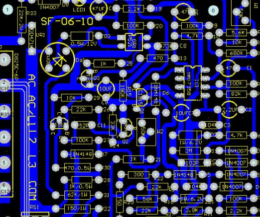
PCB board

However, general tools sold in the MARKet are usually not flexible enough to meet specifIC design requirements Therefore, customers must reflect new functional requirements to DRC tool developers, which usually requires a certain amount of money and time, especially when requirements are constantly updated Fortunately, most tool developers provide a convenient channel for customers to write their own DRC to meet specific needs However, this powerful tool has not yet been widely recognized or used This article provides a practical guide to using DRC tools to gain benefits
Since DRC must pass through PCB design, including each symbol, each pin code, each network, and each content, an unlimited number of "additional" files can be created if necessary As described in Section 4 0, DRC can mark any minor deviation that violates the design rules For example, one of the accompanying dossiers may contain all decoupling capacitors used in the design If the number of capacitors is lower or higher than the expected value, a red mark will be marketed [1] where there may be a power line dv/dt problem These profiles may be necessary, but not all commercial DRC tools can create them
Another advantage of DRC is that it can be easily updated to adapt to new design features, such as those factors that may affect design rules In addition, many other functions can be implemented once sufficient experience is gained in this field
For example, if you can write your own DRC, then you can write your own bill of material (BOM) creation tool, it can better handle specific user needs Alternatively, designers can flexibly write their own Verilog netlist analyzer in the design environment, for example, how to obtain Verilog models or time files of specific devices In fact, since DRC traverses the entire design circuit diagram, it can collect all effective information to output BOMs required for analog and/or PCB design verilog netlist analysis
It is a bit far fetched to discuss these topics without providing any code. In retrOSPect, we will use the circuit diagram acquisition tool as an example This article uses the ViewDraw tool developed by Mentor Graphics to connect to the PADS Designer product line In addition, we have adopted the ViewBase tool, which can be calLED to access the simplified C routine library of the ViewDraw database With the ViewBase tool, designers can easily use the C/C language to write a complete and efficient DRC tool for ViewDraw [2] [3] It should be noted that the basic principles discussed here also apply to any other PCB schematic tool
input file
In addition to the circuit diagram database, DRC also needs some input files to describe the specific situations that need to be handled, for example, automatically connect to the power plane using a valid grid name For example, if the power grid is named power, then the power plane will be automatically connected to the power plane using the backend package device (as applicable for ViewDrawpcbfwd) A list of input files is given below. These files must be placed in a fixed global location so that DRC can automatically find and read them, and then store the information in DRC at runtime
The file legal u pwr u net u name is optional. The file contains all the legal network naMES of the power signal, such as VCC, V3_ 3P and VDD The names of layout/wiring tools in PCB should be case sensitive Generally, VCC is different from VCC or VCC VCC can be 5.0V power supply, and V3 u 3P can be 3.3V power supply* The file legal_ pwr_ net_ Name is optional, because the backend wrapper device profile must usually contain a combination of powerline network names If you use the CADence Design Systems Allegro routing tool, the pcbfwd file name is Allegro cfg and has the following entry parameters:
Ground: VSS CGND GND GROUND
Power supply: VCC VDD VEE V3_ 3P V2_ 5P 5V 12V
If the DRC can read the allegro. Use cfg files directly instead of legal_ pwr_ net_ name, it will get better results (ie less chance of introducing errors).
Some symbols must have external power cord pins because they are not connected to the regular power cord layer For example, VCC pin of ECL device can be connected to VCC or ground; Its V-pin can be grounded or - 5.0V plane In addition, the power line pin can also reach the power line layer
he above is the explanation given by the editor of pcb circuit board company.
If you want to know more about PCBA, you can go to our company's home page to learn about it.
In addition, our company also sells various circuit boards,
High frequency circuit board and SMT chip are waiting for your presence again.

Analysis of PCB Copper Plating Process
11-07,2022


抖音二維碼

Q Q二維碼

微信二維碼
點擊
然后
聯系
然后
聯系
電話熱線
13410863085Q Q

微信

- 郵箱