鑫景福致力于滿足“快速服務,零缺陷,輔助研發”PCBA訂購單需求。


行業新聞
What losses will occur in the circuit board transmission line
This PCB transmission line contains at least two wires, one for signal and the other for return path The complex circuit board net is a combination of this SIMpler transmission line structure From the perspective of PCB design, understanding these structures (mICrostrips, striplines, and coplanars) is beneficial to designers and manufacturers
What is the loss of the transmission line?
Transmission line structures have different loss mechanisms. The total loss of PCB transmission line is calLED insertion loss (? ± t). It is the sum of conductor loss (206℃± c), dielectric loss (206℃± d), radiation loss (206℃± r) and leakage loss (206℃± l).
Because PCB has very high volume resistance, the influence of this leakage can be ignored. Radiation loss is the energy lost from the circuit due to RF radiation. This loss depends on frequency, dielectric constant (Dk) and thickness. For a specific transmission line, the loss will be higher at higher frequencies. For the same circuit, when using thinner substrate and higher Dk value, the radiation loss will be SMAller.
In this paper, we will only discuss the transmission line loss related to the conductor loss (? ± c) caused by the signal trace resistance and the dielectric loss (? ± d) caused by the PCB dielectric, which has loss tangent/dissipation factor to be measured
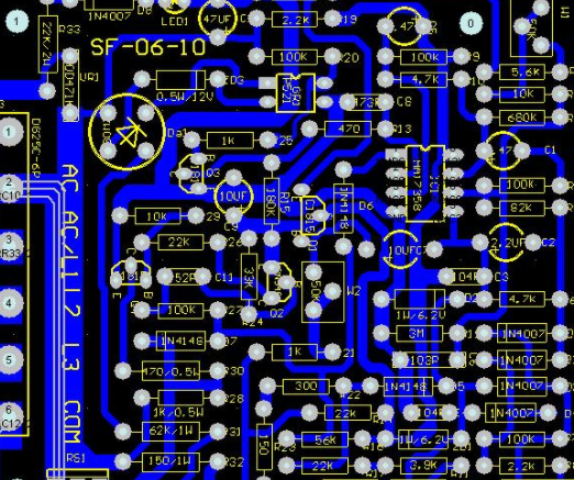
Circuit board

characteristic impedance and loss mechanism
In our previous PCB transmission line series, we gave the characteristic impedance of the transmission line (it is the impedance seen by the signal, independent of the frequency):
R=line conductor resistance of tissue length (pul)
L=inductance of line conductor loop pul
G=conductance between signal path and return path (due to dielectric) pulses
C=capacitance pul between signal path and return path (added with dielectric Dk)
For a uniform transmission line, R, L, G and C are the same at each point, and Zc has the same value at each point on the transmission line.
For the sinusoidal signal with frequency f (?=2 ? ì ì f) propagating along the line, the voltage and current equations at different points and tiMES are as follows:
Where 206? and 206? 2 Is the real part and imaginary part of PCB transmission line loss, which is obtained from the following formula:
At the frequency we are interested in, R
And: loss of PCB transmission line:
This means that the wave delays the propagation of PCB transmission line loss with each tissue length, and attenuates as it propagates along the line.
The signal attenuation coefficient of transmission line with length l is:
Attenuation or signal loss factor is usually expressed in dB.
In this case, the dB loss is proportional to the line length. Recall that we can express the above as dB loss of organization length:
We usually omit the minus sign and remember that it is a dB loss, always subtracted from the signal strength organized in dB.
The above is also called the total insertion loss of each organizational length of the transmission line, written as:
Now, the R/Z0 component of the loss is proportional to R (resistance of tissue length), which is called conductor loss and is caused by the resistance of the conductor constituting the transmission line. It was created by 'alfa' C express. The loss of GZ0 part is proportional to the conductivity of G-dielectric material, which is called the dielectric loss represented by "alfa" d.
Where R is the resistance per inch of wire.
Now, there are two conductors in the PCB transmission line -- the signal track and the return path.
Generally, the return path is a flat surface, however, the return current is not evenly distributed on the flat surface. We can prove that most of the current is concentrated on a strip whose width is 3 times of the signal track, just below the signal track.
Signal tracking resistance in PCB transmission line
Does the entire cross-sectional area of the signal path equally participate in the signal current? The answer is that this is not always the case, it depends on the frequency of the signal.
At extremely low frequencies up to about 1MHz, we can assume that the entire conductor is involved in the signal current“ α” C The resistance is the same, i.e.:
?=copper resistivity of PCB transmission line loss (organization: ohm inch)
W=track width in inches (e.g. 5 mils or 0.005 "track 50 ohms)
T=Trace thickness in inches (usually ? Oz to 10oz, i.e. 0.0007 "to 0.0014")
For example, for a 5 mil wide track:
For our purposes, we are interested in AC resistance at frequency f. Here, the skin effect enters the picture. According to the skin effect, the current with frequency f only propagates to a certain depth, which is called the skin depth of the conductor
It can be seen from the above that at 4MHz, the skin depth is equal to 1oz copper thickness, and at 15MHz, it is equal to ? Oz Copper thickness. Above 15MHz, the signal current depth is only less than 0.7 mils and decreases with the increase of frequency.
Since we focus on high-frequency behavior here, we can safely assume that T is greater than the skin depth at the frequency of interest, and we will use skin depth instead of T in the signal resistance formula. In retrOSPect, we now have:
We use 2 206206206? instead of 206206?, because technically, the current uses all the periphery of the conductor, and 2W can be replaced by 2 (W+T).
The return signal propagates along the surface closest to the signal track only in the form of thickness 206????, and its resistance can be approximated as:
The copper surface roughness at the conductor dielectric interface leads to additional conductor loss
It is important to know that the "copper conductor dielectric interface" is never smooth (if it is smooth, the copper conductor is easily peeled from the dielectric surface); it is roughened into a tooth-like structure to increase the circuit The peel strength of the conductor on the board.
The above is the explanation given by the editor of pcb circuit board company.
If you want to know more about PCBA, you can go to our company's home page to learn about it.
In addition, our company also sells various circuit boards,
High Frequency Circuit Board and SMT chip are waiting for your presence again.


抖音二維碼

Q Q二維碼

微信二維碼
點擊
然后
聯系
然后
聯系
電話熱線
13410863085Q Q

微信

- 郵箱