鑫景福致力于滿足“快速服務,零缺陷,輔助研發”PCBA訂購單需求。


行業新聞
About PCB schematic design of mechanICal keyboard
Before PCB design was used for mechanical keyboard, we need to follow some steps
Software configuration includes:
We will use KiCAD to design the keyboard PCB. Now, first download and install it so that you can follow all the technologies and techniques we have in common. KiCad is one of the most widely used design software. Recall that you can get many tutorials on how to design in Kicad software. If you have already instalLED it, we can start. One thing you need to do is make sure you have all the official KiCad libraries.
Plan:
Start KiCad first, and then you will see a screen with many options. Now click New Item. Then give your project a name of your own, such as the keyboard PCB or any name you like. Now we will design the schematic diagram. So be careful
First, click the ". sch" file twice, and you will see a completely blank table.
Now we must add a component library. If you are looking at the top of the window, click Preferences>Component Library. Now click Add and try to find the "keyboard_ parts. lib" file from the shell library. You can then follow the instructions and recommendations of the software. There are so many tutorials online that you can easily view and install the library.
Now, first, we will recommend a basic command list:
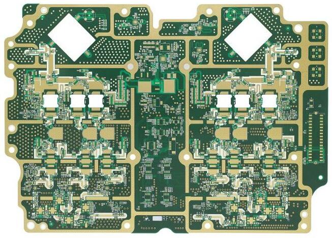
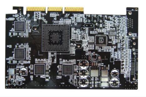
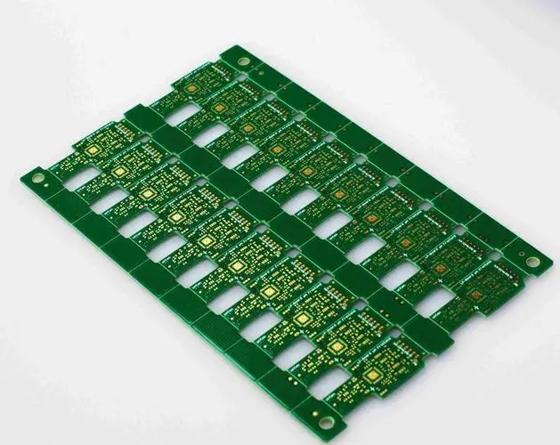
Circuit board

"M: Lift the part and move it
g: Drag and move components up while keeping the cables connected
c: Copy Components
e: Edit Component
r: Rotating parts
y: Mirror component
Delete: Delete components
ESC: Abort! “
Then click Place>Component. Now you can see that your horse looks like a pencil. Just click anywhere on the page to find ATMEGAA32U4 in the library installation.
Click OK, and then click the footprint to place the component. We have to edit the component and change the reference from U to U1.
We will place glasses Glass is an important part of all available components on the aircraft Keyboard PCB because it determines the playing speed of the keyboard Now, we will place the component "XTAL_GND" next to the controller SIMply change the reference to X1
One thing to remember is that too much noise may interfere with the controller signal. This should be avoided by using two decoupling capacitors. Now, we will use a crystal with a charging capacitance of 18pF. Recall that the decoupling capacitors C1 and C2 we need are 22pF. Finally, we will add a GND symbol and connect everything
Next, we will add four 0.1uF decoupling capacitors C1, C2, C3, C4 and a 4.7uF capacitor called C7.
Look at pin 13. This is the reset pin. We want to add a button switch to this pin so that it can be easily reset when needed. To do this, we will add a switch "SW u PUSH" and name it SW1. Now we must add a 10k pulp register using this switch called R1.
Now we must add a USB port. Recall, go to the library and select "usb u mini u micro u B", add it to the worksheet, and name it J1. Now, if you look at USB, there are various pins, such as VUSB, D -, D+, ID, GND, SHIELD. Now connect the VUSB to the VCC and then to the UVcc of the controller. D and D+from the controller and USB will be connected to two 22 ohm resistors called R1 and R2. The grounding and mask layers will be short circuited, and then connected to the UGND and UCap of the controller through a 1uF capacitor.
Then, check whether all VCC connections and GND connections are correctly connected, and then proceed to the next step. However, if they are not connected, connect them correctly. Remember that if you use an included ADC, you may need to place a capacitor between AVCC and VCC.
Now we will organize the switch matrix. In this tutorial, we will show you a 2X2 matrix. In this case, first in, first in, select "KEYSW" for the switch and "D" for the diode element. Now connect them to K1 and D1 respectively, and connect K2 to D2. As mentioned earlier, it is two 2 * 2 matrices. Then we must perform the same processing on K3, K4, D3 and D4.
As you can see, there are many unused components MARKed as unused pins. Click the blue X button on the right to select all unconnected pins on the controller and USB port.
After final completion, the mechanical schematic board PCB is successfully completed
The above is the explanation given by the editor of pcb circuit board company.
If you want to know more about PCBA, you can go to our company's home page to learn about it.
In addition, our company also sells various circuit boards,
High Frequency Circuit Board and SMT chip are waiting for your presence again.


抖音二維碼

Q Q二維碼

微信二維碼
點擊
然后
聯系
然后
聯系
電話熱線
13410863085Q Q

微信

- 郵箱