鑫景福致力于滿足“快速服務(wù),零缺陷,輔助研發(fā)”PCBA訂購單需求。


行業(yè)新聞
Master the backstepping steps and easily learn the schematIC diagram of PCB board
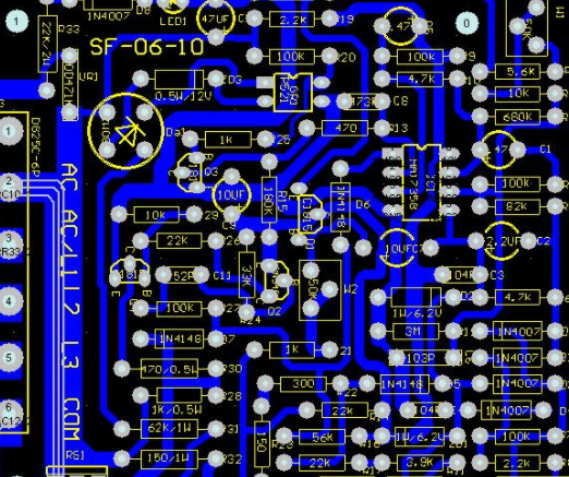
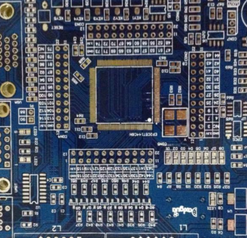
PCB board
Many people do not know what PCB copying is. Some people even think that PCB copying is a kind of imitation. In our understanding, copycat means imitation, but PCB copying is not imitation. The purpose of PCB replication is to learn foreign electronic circuit design technology, and then absorb the design scheme, and then use it to develop and design more products. With the continuous development and deepening of the board reading industry, today's PCB board reading concept has expanded to a wider range. It is no longer limited to the reproduction of SIMple circuit boards and Kiro, but also involves the secondary development of products and the research and development of new products. For example, through the analysis of the existing product technical files, design ideas, structural features, process technology, etc., it can provide feasibility analysis and competitive reference for the R&D and design of new products, assist the R&D and design units to track the development trend of science and technology, timely adjust and improve the product design scheme, and develop new products with MARKet competitiveness.

Through the selection and partial modification of scientific and technological archives, the PCB copy process can realize the rapid updating, upgrading and secondary development of various electronic products. According to the file drawings and schematic diagrams selected from the copied boards, the designers can also optimize the design and modify PCB according to the wishes of customers. On this basis, new functions can also be added to the product or functional features can be redesigned, so that products with new functions can quickly emerge in a new manner, not only with their own intellectual property rights, but also to win the market, which is the first opportunity to bring double benefits to customers. Whether used to analyze PCB principles and product working characteristics in reverse research or used as the basis and basis for PCB design in forward design, PCB schematics play a special role. Then, how to reverse the schematic diagram of PCB according to the file diagram or physical object, and what is the reverse process. What kind? What details should I pay attention to?
1. Reverse thrust steps
1) Record PCB related details
After obtaining the PCB, first record the model, parameters and positions of all components on the paper, especially the orientation of the diode, transistor and IC notch. Take two pictures of component positions with a digital CAMera. Many PCB boards are getting bigger and bigger. The top diode triode is not obvious.
2) Scanned image
Remove all components and remove the tin from the PAD hole. Clean the PCB board with alcohol and place it in the scanner. When the scanner scans, it needs to slightly increase the number of scanning points to obtain a clearer image. Then gently polish the top and bottom layers with gauze until the copper film becoMES bright, put it into the scanner, start PHOTOSHOP, and use the color method
The two layers are swept in respectively. Please note that the PCB must be placed horizontally and vertically in the scanner, otherwise the scanning image cannot be used.
3) Adjust correction image
Adjust the contrast and brightness of the canvas to make the parts with copper film form a strong contrast with the parts without copper film, and then turn the secondary image into black and white to check whether the lines are clear. If not, repeat this step. If it is clear, please save the picture as black and white BMP files TOP BMP and BOT BMP. If you find a problem with the picture, you can also use PHOTOSHOP to repair it
And amendments.
4) Verify the position consistency of PAD and VIA
Convert two BMP files to Protel files, and convert them to two-layer files in Protel. If the positions of pads and through-hole through the two layers are basically the same, the previous steps are well done. If there are any deviations, repeat step 3. Recall that PCB copying is a very patient job, because a SMAll problem will affect the quality and matching after copying
degree
5) Paint Layer
Convert BMP of TOP layer to TOP PCB. Note that it should be converted to a SILK layer, the yellow layer. Then, you can trace lines on the TOP layer and place components according to the drawing in step 2. Delete SILK layer after drawing. Repeat this operation until all layers are drawn.
6) TOP PCB and BOT PCB assembly diagram
In PROTEL, call TOP PCB and BOT PCB to combine them into a picture.
7) Laser printing top layer and bottom layer
Use the laser printer to print TOP LAYER and BOTTOM LAYER (1:1 scale) on the transparent film, place the film on the PCB, and compare whether there are errors. If it is correct, you are finished.
8) Testing
Test whether the electronic technical efficiency of the circuit board is the same as that of the original circuit board. If it is the same, it is really finished.
2. Pay attention to details
1) Reasonably divide functional areas
When reverse designing the schematic diagram of a good PCB, reasonably dividing the functional area can help engineers reduce some unnecessary troubles and improve the drawing efficiency. In general, the components with the same function on the PCB board will be arranged in a centralized way, so that the functional division can provide a convenient and accurate basis for reversing the schematic diagram. however
Division is not arbitrary. It requires engineers to have a certain understanding of electronic circuit related knowLEDge. First, find out the components in a functional unit, and then find out other components of the same functional unit according to the routing connection to form a functional partition. The formation of functional partitions is the basis of the schematic diagram. In addition, don't forget originality in this process
Using the serial numbers of components on a circuit board, they can help you divide functions more quickly.
2) Calibration reference
This reference piece can also be said to be the main component PCB network used at the beginning of the schematic diagram. After the reference pieces are determined, they are drawn according to the pins of these reference pieces, which can ensure the accuracy of the schematic diagram to a greater extent. For engineers, the determination of benchmarks is not complicated. Generally speaking, they can choose to play a major role in the circuit
As reference pieces, components and parts of are usually large in size, with many pins, which are easy to draw, such as integrated circuits, transformers, transistors, etc., and can be used as appropriate reference pieces.
3) Correctly distinguish the lines and reasonably arrange the wires
In order to distinguish ground wire, power wire and signal wire, engineers also need to have relevant knowledge of power supply, circuit connection, PCB wiring, etc. The differences between these circuits can be analyzed from the connection of components, the width of circuit copper foil and the characteristics of electronic products. In the wiring diagram, in order to avoid line crossing and mutual penetration, a large number of ground wires can be used
With the grounding symbol, different lines with different colors can be used for different lines to ensure clear identification. Special marks can also be used for various components, or even for drawing and combining unit circuits separately.
4) Master the basic framework and learn from similar diagrams
Engineers need to be proficient in the framework composition and schematic drawing method of some basic electronic circuits. They should not only be able to directly draw some simple and classic basic composition forms of unit circuits, but also be able to form the overall framework of electronic circuits. On the other hand, do not neglect that the same type of electronic products have some similarities in the schematic diagram
On the basis of accumulated experience, teachers can fully learn from similar circuit diagrams to reverse the schematic diagram of new products.
5) Check and optimize
After this schematic diagram is drawn, it can be said that the reverse design of PCB schematic diagram can only be completed after testing and verification The nominal values of components sensitive to PCB distribution parameter need to be checked and optimized According to the PCB file relationship diagram, the schematic diagram needs to be compared, analyzed and checked to ensure that it is completely consistent with the file relationship diagram
How to make a good PCB
10-26,2022


抖音二維碼

Q Q二維碼

微信二維碼
點(diǎn)擊
然后
聯(lián)系
然后
聯(lián)系
電話熱線
13410863085Q Q

微信

- 郵箱