鑫景福致力于滿足“快速服務,零缺陷,輔助研發”PCBA訂購單需求。


PCBA加工
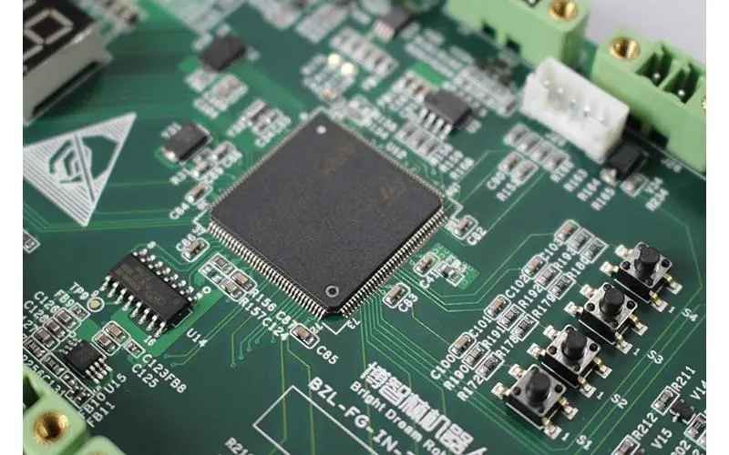
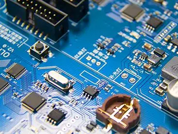
Printed circuit board {PCB circuit board}, also known as printed circuit board, is the provider of electrICal connection of electronIC components. It has been developed for more than 100 years; Its design is mainly layout design; The main advantage of using circuit board is to greatly reduce wiring and assembly errors, improve the level of automation and production labor rate.
According to the number of circuit board layers, it can be divided into single panel, double panel, four-layer board, six-layer board and other multi-layer circuit board.

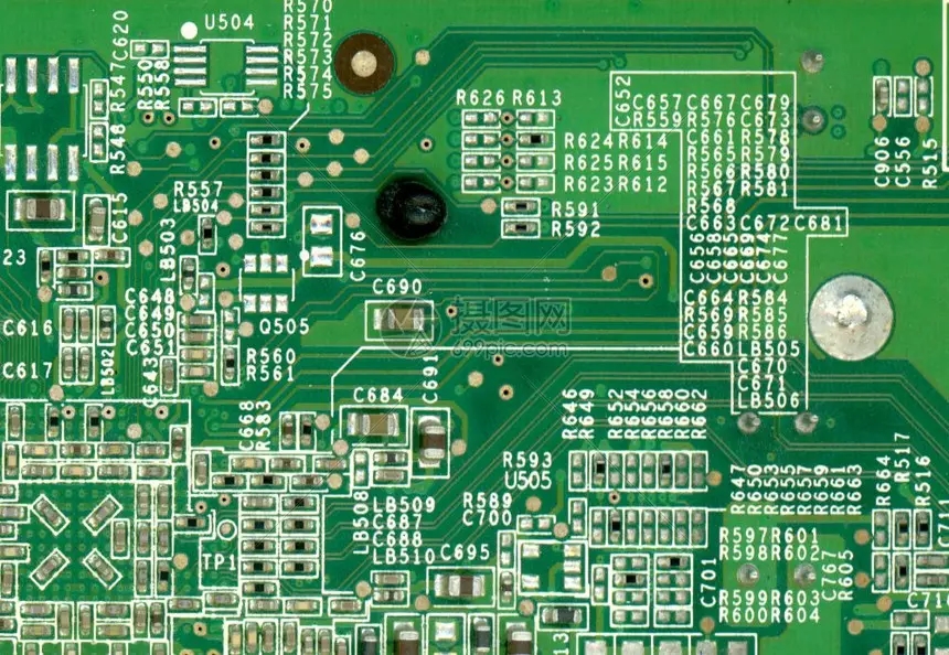
Because the printed circuit board is not a general terminal product, so in the name of the definition of a slightly confused, such as: personal computer motherboard, calLED the motherboard, and not directly called the circuit board, although there is a circuit board in the host board, but not the same, so the assesSMEnt of the industry when the two related but can not say the same. Another example: because there are integrated circuit parts loaded on the circuit board, so the news media called it IC board, but in essence it is not equivalent to printed circuit oard. We usually say that the printed circuit board is a bare board - that is, no components on the circuit board.
classification Folded single panel
On the most basic PCB, parts are concentrated on one side and wires are on the other. Because the wire is present on only one side, this PCB is called single-sided.
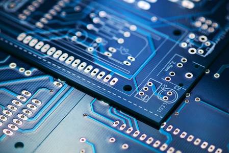
The board has wiring on both sides, but to use the wires on both sides, there must be a proper circuit connection between the two sides. This "bridge" between circuits is called a pilot hole (VIA). Pilot holes are SMAll, metal-filled, or metal-coated holes in a PCB that can be connected to wires on both sides. Because the area of the double panel is twice as large as that of the single panel, the double panel solves the difficulty of the staggered wiring in the single panel (it can be guided to the other side through holes), and it is more suitable for the more complex circuit than the single panel.
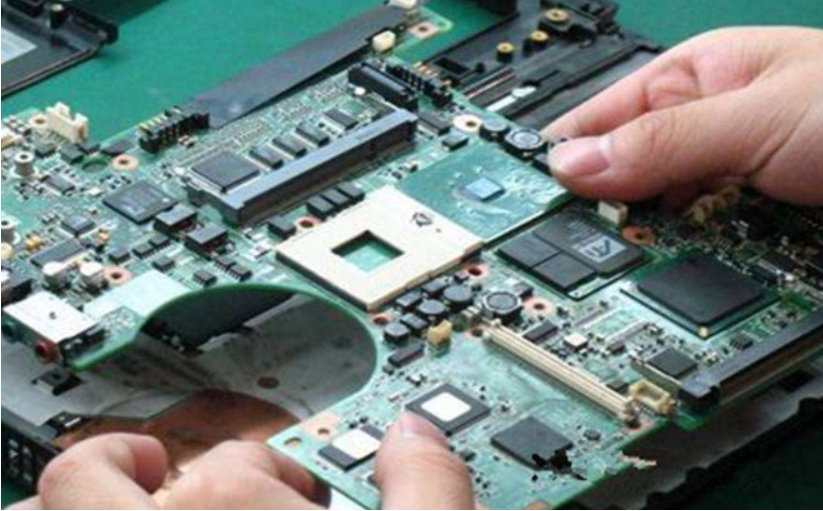
Folding multilayer board
In order to increase the area of wiring, multi - layer board used more single or double - sided wiring board. With a double lining, two one-way for outer layer or two double lining, two blocks of single outer layer of the printed circuit board, through the positioning system and alternate insulation adhesive materials and conductive graphics interconnection according to design requirement of printed circuit board becoMES four, six layer printed circuit board, also known as multilayer printed circuit board. The number of layers of the board does not mean that there are several independent wiring layers. In special cases, empty layers are added to control the thickness of the board. Usually, the number of layers is even and contains the outermost two layers. Most host boards are 4 to 8 layer structures, but the technical theory can be up to 100 layer pcb board. Most large supercomputers use fairly multi-layered mainframe boards, but since these computers can be replaced by clusters of regular computers, super-multi-layered boards have fallen out of use. Because the layers in the PCB are tightly integrated, it is generally not easy to see the actual number, but if you look closely at the host board, you can still see it.
Fold the history
Before the advent of printed circuit boards, electronic components were connected directly by wires to form a complete circuit. In modern times, circuit boards exist only as effective experimental tools, while printed circuit boards have become the absolute ruling position in the electronics industry.
At the beginning of the 20th century, in order to SIMplify the production of electronic machines, reduce the wiring between electronIC parts, reduce production costs and other advantages, so people began to study the method of printing to replace wiring. For 30 years, engineers have bf the United States printed circuit patterns on the insulating substrate, and then established conductors for wiring by electreen proposing to add metal conductors to insulated substrates for wiring. The most successful was in 1925, when Charles Ducas ooplating.
It wasn't until 1936 that Paul Eisler, an Austrian, published foil technology in Britain, using printed circuit boards in a radio set; In Japan, Yoshimonsuke Miyamoto successfully applied for a patent on the "rapmover method with the method of spraying and moping (license No. 119384)." Of the two, Paul Eisler's method was most similar to today's printed circuit boards, a practice known as subtraction that removes unwanted metals. Charles Ducas and Yoshisuke Miyamoto, on the other hand, add only the required wiring, known as MARKups. However, because of the high heat of electronic parts at that time, the two substrates were difficult to work together, so that no formal practical use, but also the printing circuit technology further.
In 1941, the United States painted copper paste on talc for wiring to make close connections.
In 1943, the Americans made extensive use of the technology in military radios.
In 1947, epoxy began to be used for manufacturing substrates. At the same time NBS began to study the printing circuit technology to form coils, capacitors, resistors and other manufacturing technology.
In 1948, the United States officially approved the invention for commercial use.
Since the 1950s, vacuum tubes have been largely replaced by transistors with lower heat output, and printed circuit plates have been widely adopted. At that time, etching foil film technology was the mainstream.
In 1952 Japan used a glass substrate with silver paint for wiring; And the paper phenolic substrate (CCL) made of phenolic resin with copper foil as wiring.
In 1951, the appearance of polyimide, the heat resistance of the resin further, and also the manufacture of polyamide substrate.
In 1953, Motorola developed a dual panel with an electroplated through-hole method. This method is also applied to the later multilayer circuit board.
Printed circuit boards were widely used for 10 years in the 1960s, and their technology beCAMe increasingly mature. Since the advent of Motorola's dual panels, multilayer printed circuit boards have appeared, increasing the ratio of wiring to substrate area.
In 1960, V. Dahlgreen created a flexible printed circuit board by attaching a foil film with a circuit printed on it to a thermoplastic plastic.
In 1961, Hazeltine Corporation of the United States made reference to the electroplating through-hole method to produce a multilayer plate.
In 1967, Plated- Up Technology, one of the additive methods, was published.
In 1969, FD-R produced a flexible printed circuit board based on polyimide.
In 1979, Pactel published one of the "Pactel method".
In 1984, NTT developed the "Copper Polyimide method" for thin film circuits.
In 1988, Siemens developed Microwiring Substrate for laminated printed circuit boards.
In 1990, IBM developed the Surface Laminar Circuit Board (SLC), a layered printed Circuit board.
In 1995, Matsushita developed the AL ⅳ H layered printed circuit board.
In 1996, Toshiba developed the Bit layered printed circuit board.
In the late 1990s, when many additional layer printed circuit board schemes were proposed, additional layer printed circuit board was also formally used in a large number of practical, until now.

Fold development
In the past ten years, the manufacturing industry of Printed Circuit Board (PCB) in our country has been developing rapidly, Printed Circuit Board (Printed Circuit Board, short for PCB) is Printed in both the total production value and total production volume ranking the first in the world. China has become the world's most important manufacturing base for printed circuit boards, with its industrial distribution, cost and market advantages, as electronic products change rapidly and price wars change the structure of supply chains.
The printed circuit board develops from single layer to double panel, multi-layer board and flexible board, and continues to develop to high precision, high density and high reliability direction. Continuously reduce the size, reduce the cost, improve the performance, so that the printed circuit board in the future of the development of electronic products, still maintain a strong vitality.
In the future, the development trend of printed circuit board manufacturing technology is to develop in the direction of high density, high precision, fine aperture, thin wire, small spacing, high reliability, multi-layer, high speed transmission, light weight and thin.
According to the survey data of "2013-2017 China printed circuit board manufacturing Industry Market Outlook and Investment Opportunities Analysis Report" by Qianqian.com, in 2010, there were 908 printed circuit board manufacturing enterprises above designated size in China, with total assets of 216.176 billion yuan; The sales revenue reached 225.796 billion yuan, up 29.16% year on year; The total profit reached 9.403 billion yuan, up 50.08% year on year.

抖音二維碼

Q Q二維碼

微信二維碼
點擊
然后
聯系
然后
聯系
電話熱線
13410863085Q Q

微信

- 郵箱