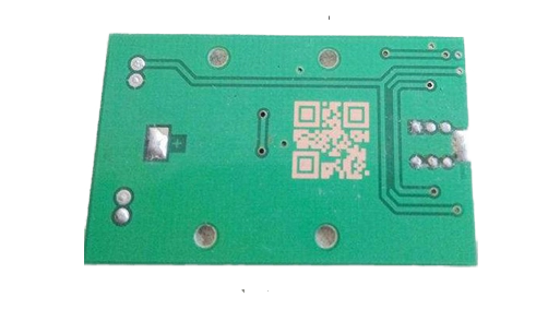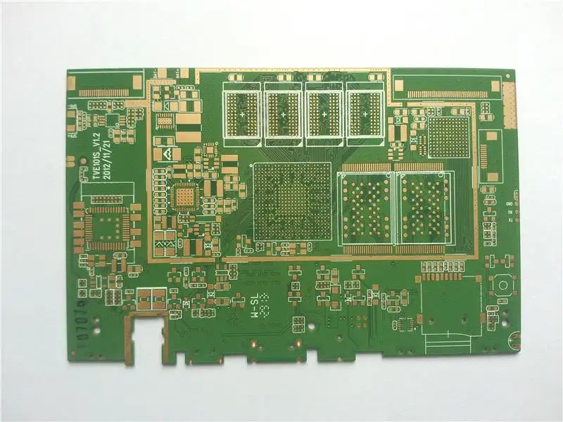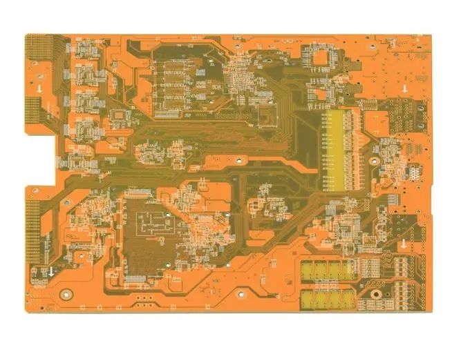

There is an appropriate capacitor near the power supply pin of the IC, and the IC output voltage can jump quickly. However, the problem will not stop there. Since capacitance is a characteristic of finite frequency response, electricity cannot generate the harmonic power required to drive the full band IC output cleanly. In addition, the formed transient voltage on the power bus forms a voltage drop across the coupling path, which is the main cause of common mode EMI interference. How should these problems be solved?
PCB design

Compared with the circuit board on the IC, the power supply layer of the peripheral IC is regarded as an excellent high-frequency capacitor used to recover some energy leaked from the discrete capacitor to the high-frequency energy provided by the clean output. Moreover, because the excellent power layer inductance is very SMAll and the inductance of the synthesized transient signal is also very small, the common mode EMI is reduced.
Of course, the PCB wiring from the power layer to the IC power supply pin is a faster rise of digital signals. Since it is better to directly connect to the IC power supply pin layout, it is necessary to describe it separately and as short as possible.
In order to control that common mode EMI is a decoupLED power layer, it is useful to have a sufficiently low inductance, and it must be properly designed as a PCB power layer and a pair of power layers. Some people may ask, how good is it? The answer to the question depends on the hierarchical structure of the power supply, the materials between the layers and the operating frequency (a function of IC rise time). Typically, the power supply layer spacing is 6 mils, the interlayer is material, and the equivalent capacitance per square inch of power level is about 75 pF. Obviously, the spacing between smaller layers is larger capacitance.
The 300PS 100 rise time of the device is not much. According to the current development speed of IC, the rise time in the range of 100-300PS accounts for a high proportion. Circuits with a rise time of 100 to 300 ps do not impose a 3 mil interval on most applications. At this time, when the layer spacing is less than 1 mil, it is necessary to replace the FR4 dielectric material with a high dielectric constant material. Now, ceramics and ceramic plastics can meet the requirements of pcb design for 300 ps rise time circuit.
New materials and methods, however, will be used in the future. It is enough to process harmonics and make the transient signal low enough from the normal single day interval and FR4 dielectric material 6mil 3 rise time circuit to 3ns. That is, common mode EMI may drop very low.
然后
聯(lián)系
電話熱線
13410863085Q Q

微信

- 郵箱


