鑫景福致力于滿足“快速服務(wù),零缺陷,輔助研發(fā)”PCBA訂購(gòu)單需求。


PCBA方案設(shè)計(jì)

design of PCB automatic Detection System Based on Image Processing
High precision, large-scale, fast, and real-time automatIC optical inspection system PCB board defects are studied, and hardware structure and software system are designed respectively The system is mainly composed of two-dimensional motion platform, motor control module, image acquisition module, image processing module, and the results are displayed in the analysis module The improved stepping motor driving mode, subdivision driving, and improved image recognition algorithm ensure the accuracy of the system. The design of one click automatic detection improves the detection speed The experimental results show that the system can quickly and accurately detect the defects on the workpiece surface of PCB, and has certain practical value and development value
The electronic product part, this printed circuit board, is the information carrier integrating various electronIC components It has been widely used in various fields and is an indispensable part of electronic products The quality of PCB has become a long-term determinant, and electronic products work normally and reliably With the development of science and technology, high-density development trend, high complexity, and high-performance PCB products continue to challenge the quality inspection of PCB boards
Due to limited access and other factors, high cost and low efficiency, traditional PCB defect detection methods have gradually faiLED to meet the needs of modern detection Therefore, the research and implementation of PCB defect automatic detection system has important aCADEMIc and economic value AOI (Automatic Optical Inspection) technology has received more and more attention, a defect detection technology researched at home and abroad for PCB boards, and detection methods based on image processing have also become the mainstream of automatic optical detection In this paper, the large field of vision, high precision, fast real-time automatic detection system PCB research defects through image processing technology, designed the hardware structure and software calculation process By improving the motor driven pipeline and designing the one key automatic detection software, the detection speed of the system is greatly improved, and the accuracy of the detection results is improved by the improvement of the defect identification algorithm of the result analysis module
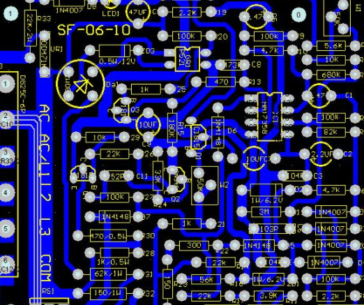
Circuit board

1. System structure
The PCB defect automatic detection system is mainly composed of motion control module, image acquisition module, image processing module, and result analysis module The working process of the system is as follows: the upper computer controls the motion of the stepping motor, the stepping motor drives the motion of the two-dimensional platform, transfers the CCD CAMera to the top of the PCB to be detected, and collects the images of large scenes on the PCB, and the collected images are sent to the image acquisition card Connect to the host computer, and the host computer software will splice and preprocess the collected images, accurately locate and calibrate the processed images, perform template matching, image recognition, image morphology processing, etc. through image segmentation, And obtain the defect detection results The system design includes hardware design and software design The system software and hardware work together to form a whole
2. System hardware design
The hardware design of the PCB defect automatic detection system mainly includes two-dimensional motion platform, motor motion control board, motor drive board, CCD camera, image acquisition card, and a computer
2.1 CCD camera and frame grabber
The main characteristic parameters of the CCD camera include camera format, photosensitive surface size, point size, resolution, electronic shutter speed, synchronization system method, illumination, consideration, signal to noise ratio, etc The camera format and online detection determine the sampling frequency of the image acquisition card The balance of the size of the sensitive surface, the size of the points, the resolution, and the magnification of the imaging lens system depend on the measurement range and accuracy Considering the above factors and system requirements, the rack grabber, also known as video capture card, is a video card The main function of the frame acquisition card is to convert the continuous analog video signal of the camera into discrete digital quantity Its basic principle is that the input selection module processes video output signals of various formats from the camera to form video signals that can be recognized by the image capture card After analog video signal conversion, it is stored in the frame buffer memory of the card. The specific image transmission is controlled by the computer CPU through the computer bus, and finally stored in the computer memory or hard disk for image processing The model of the image acquisition card used in this design is NV7004-N, which converts the analog signal of CCD camera into digital signal and transmits it to the upper computer for real-time display to complete the image acquisition function
2.2 Motor Motion Controller and Precision 2D Motion Platform
The motion controller of the PCB defect automatic detection system is a self-designed single chip microcomputer control board. The chip is AT89S52 single chip microcomputer produced by ATMEL company. The control board communicates with the upper computer through RS-232 serial communication interface The command is sent to the control board through the operation human-machine interface, and the control board outputs the control signals and square wave signals of different frequencies to the stepping motor drive board to control the speed, direction, and moving distance of the stepping motor The two-dimensional motion platform is composed of two precision motion guides produced by Japanese SUS Company The moving guide rail is ball screw type, very precise, with very SMAll error The stepping motor is connected with the moving guide rail to drive the movement of the guide rail Stepping motor is a two-phase four wire hybrid stepping motor produced by TAMAGAWA, Japan The stepping motor runs stably and has low noise
2.3 Motor drive
In fact, the drive of the stepping motor is to control the current of each phase excitation winding of the stepping motor, so as to change the synthetic direction of the internal magnetic field of the stepping motor and make the stepping motor rotate The magnitude of the resultant magnetic field vector generated by the current of each phase excitation winding determines the rotating torque of the stepping motor, and the angle between two adjacent resultant magnetic field vectors determines the stepping angle This paper introduces two important concepts of stepping motor: pitch angle, z and step angle, n The pitch angle of the stepping motor refers to the angle between two adjacent stable magnetic fields when the stepping motor is running Stepping angle refers to the angular displacement of the rotor of the stepping motor relative to the rotation of the pulse signal
The step angle is not only related to the number of teeth of the motor, but also to the number of beats of the motor. The pitch angle of the stepping motor, z and the step angle, n can be expressed as: the subdivision of the stepping motor is based on the ideal symmetry of each phase winding of the stepping motor and the strict positive rotation of the pitch angle characteristics. The size and ratio of the current in the winding reduce the step angle to 1% to 1% of the original, thus improving the resolution of the stepping motor. Taking a two-phase stepping motor as an example, if the number of teeth of the motor is 50 and the number of running beats is a single four beat mode, the step angle is 360 degrees (50 * 4)=1.8 degrees (usually called full step), when shooting, it is 8, and the step angle is 360 degrees/(50 * 8)=0.9 degrees (usually called half step 0). Compared with the four shot mode, the step angle ? n is doubled, which realizes the secondary subdivision of the step angle. In the case of a certain number of beats, the more teeth, the smaller the step angle. However, due to the limitation of manufacturing technology, the number of teeth cannot be too many. In addition, the step angle of this stepping motor cannot be too large. Small
The step angle can also be changed by changing the number of beats of the step motor. The number of beats refers to the number of pulses or conduction state required to complete the periodic change of magnetic field, or the number of pulses required for the motor to rotate through the pitch angle. When determining the phase number of the motor, the number of beats will also be determined. The step angle is reduced by adding the number of teeth and phase of the stepping motor. The reduction of the step angle is very limited, which is difficult to meet the Production requirements. The common method of motor subdivision drive is equal amplitude uniform rotation of current vector. The current vector constant amplitude uniform rotation method can make the step angle after subdivision uniform and the output torque constant.
The specific method is to make their phase windings pass through the phase difference respectively. If the sinusoidal current is 2 ?/m and the amplitude is equal, the current combination vector or magnetic field vector will rotate in space, and the amplitude of the combination vector will remain unchanged. For example, for a four phase hybrid stepping motor, sine wave currents with phase difference of 207ì/2 and equal amplitude are respectively provided to the phase windings. In order to obtain as many circular synthetic magnetic fields as possible and make the step angle change uniformly, it is ideal to use the step sine waveform for the current reference signal of each phase winding.
Take 8 subdivisions of a four phase stepping motor as an example, and insert 7 stable intermediate states into each phase After subdivision, the current of each phase rises or falls in steps of 1/4. The angle will be completed in 8 steps, and 8 step angle subdivision can be realized More subdivisions and smaller current changes greatly reduce the vibration and noise of the motor When the step sine wave is used to subdivide the current, the more steps (that is, the more subdivisions), the closer the waveform is to the sine wave, the smaller the step current and the smaller the step angle This greatly reduces the step loss rate when the stepping motor is running It reduces the noise and vibration when the stepping motor runs, and also makes the stepping motor run more stable and easier to control the PCB


抖音二維碼

Q Q二維碼

微信二維碼
點(diǎn)擊
然后
聯(lián)系
然后
聯(lián)系
電話熱線
13410863085Q Q

微信

- 郵箱