鑫景福致力于滿足“快速服務,零缺陷,輔助研發”PCBA訂購單需求。


PCBA方案設計

EMC design of PCB Microcontroller System
The following describes the electromagnetic compatibility of the PCB microcontroller software processing design
1 Factors affecting EMC
1.1 Voltage: higher supply voltage means greater voltage amplitude and more EMIssion, while lower supply voltage will affect sensitivity
1.2 Frequency: High frequency generates more emissions, and periodIC signals generate more emissions In the high frequency microcontroller system, when the equipment is switched, a current SPIke occurs; In analog systems, current spikes occur when the load current changes
1.3 Grounding: among all EMC problems, the main problem is caused by improper grounding There are three signal grounding methods: single point, multipoint, and mixed When the frequency is lower than 1MHz, the single point grounding method can be used, but it is not applicable to high frequency; In high frequency applications, multi-point grounding is used Hybrid grounding is a single point grounding method for low frequency and a multi-point grounding method for high frequency The layout of ground wire is the key. The ground circuit of high frequency digital circuit and low level analog circuit cannot be mixed as much as possible
1.4. PCB design: Proper printed circuit board (PCB) routing is critical to preventing EMI
1.5 Power decoupling: when the equipment is switched, transient currents are generated on the power line, and these transient currents must be attenuated and filtered The transient current/dt source from high di leads to grounding and track "trigger" voltage, and high di/dt generates large scale high-frequency current, which excites components and radiates cables The change of current and inductance through the conductor will cause voltage drop, which may be caused by the decrease of inductance or the change of current with time
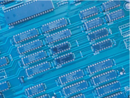
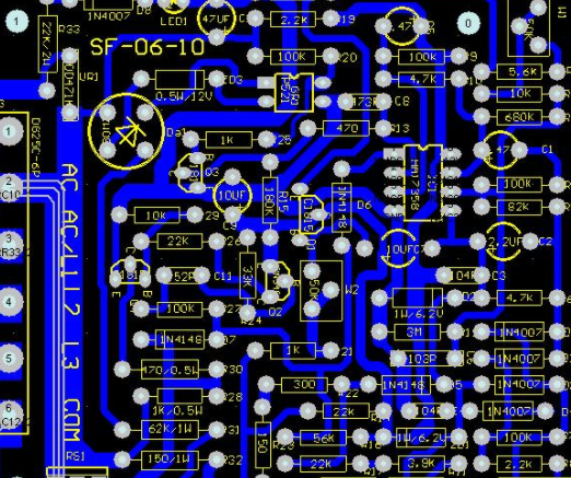
PCB board

2. This hardware processing method of interference measures
2.1 PCB with electromagnetic compatibility design
The PCB is the support of circuit components and equipment in the single-chip microcomputer system, which provides the power connection between circuit components and equipment With the rapid development of electronic technology, the density of PCB is getting higher and higher The design of quality PCB board has a great influence on the electromagnetic compatibility of single chip microcomputer system Practice has proved that even if the circuit schematic diagram is correctly designed and the printed circuit board is improperly designed, it will have a negative impact on the reliability of the single-chip microcomputer system For example, if two thin parallel lines on the printed circuit board are very close, the signal waveform and reflected noise at the end of the transmission line will be delayed Therefore, when designing the printed circuit board, attention should be paid to using the correct method, following the PCB design, and meeting the anti-interference design requirements To obtain the efficiency of electronic circuits, component layout and wire layout are very important
2.2 Input EMC design/output
In the single chip microcomputer system, I/O is also the transmission line of the interference source and the pickup source for receiving RF interference signals We generally take effective measures when designing:
1) Use the necessary common mode/differential mode suppression circuit, and take certain filtering and anti electromagnetic shielding measures to reduce interference
2) Take various isolation measures (such as photoelectric isolation or magnetoelectric isolation) as far as possible to block the spread of interference.
2.3 Design of MCU reset circuit
In the MCU system, the watchdog system plays a particularly important role in the operation of the entire MCU Because it is impossible to isolate or remove all interference sources, once the CPU interferes with the normal operation of the program, the combination of reset system and software becoMES an obstacle to effective error correction defense There are two commonly used reset systems:
1) External reset system. The external "watchdog" circuit can be designed by ourselves or built with a special "watchdog" chip However, each has its advantages and disadvantages Most special "watchdog" chips cannot respond to low-frequency "dog feeding" signals, but can respond to high-frequency "dog feeding" signals, so that "dog feeding" signals can be generated at low frequencies The reset action will not occur under the high-frequency "feed dog" signal In this way, if the program system falls into an infinite loop and the loop happens to have a signal of "feeding the dog", the reset circuit cannot be realized Correct function However, we can design a system with band-pass "dog feeding" circuit and other reset circuits, which is a very effective external monitoring system
2) Nowadays, more and more single-chip microcomputers have their own on-chip reset systems. In summary, users can easily use their internal reset timers However, some models of SCM have too SIMple reset commands. In retrOSPect, there is also a "feed dog" command, such as the infinite loop above, which makes it lose its monitoring function Some microcontrollers have better on-chip reset instructions Usually, they write the "feed dog" signal to multiple instructions in a fixed format and execute them sequentially If there is some error, the "Dog Feeding" operation is invalid The reliability of reset circuit is improved
2.4 Oscillator
Most microcontrollers have an oscillator circuit coupLED to an external crystal or ceramic resonator. On PCB board, the lead of external capacitor, crystal or ceramic resonator shall be as short as possible RC oscillators are potentially sensitive to interference signals and can produce very short clock cycles. Crystal or ceramic resonators are selected In addition, the case of quartz crystal shall be grounded
2.5 Lightning protection measures
The single-chip microcomputer system used outdoors or the power lines and signal lines introduced into the room from the outside should be considered against the lightning strike of the system. Common lightning protection devices are: gas discharge tube, television, etc The gas discharge tube is used when the power supply voltage is greater than a certain value, usually tens or hundreds of volts. The gas is decomposed and discharged, and the strong impulse pulse on the power line is guided to the ground TVS can be regarded as two parallel and opposite Zener diodes, which will turn on when the voltage at both ends is higher than a certain value Its characteristic is that it can transiently pass hundreds or thousands of A current
3. Software processing method for interference measures
The interaction signal generated by the electronic interaction source cannot be completely eliminated in some specific cases (such as in some cases where the electronic environment is relatively hard), and will be input to The CPU processing unit Especially for devices using bistable storage such as RAM, it often flips under strong interference, making the original storage "0" become "1", or "1" become "0"; The timing and data of some serial transmission will change due to interference; More seriously, it will destroy some important data parameters, etc; The consequences are often very serious In this case, the quality of software design directly affects the anti-interference capability of the whole system
3.1 The program will be roughly in the following situations due to electromagnetic interference:
1) The program runs away. This is a common interference result Generally speaking, a good reset system or software framework measurement system is enough, and it will not have too much impact on the entire operating system
2) Infinite loop or abnormal program code running. Of course, this infinite loop and exception code is not intentionally written by the designer We know that program instructions are composed of bytes, some are unit tuple instructions, and some are multi byte instructions When interference occurs, the PC pointer appears Change. After that, the original code is reorganized to generate unpredictable executable code. Then, this error is fatal. It may modify important data parameters, and may generate unpredictable control of a series of error states, such as output
3.2 Measures for storage of important parameters
In general, we can use error detection and correction to effectively reduce or avoid this situation According to the principle of error detection and correction, the main idea is that when data is written, a certain number of check codes are generated according to the written data and stored together with the corresponding data; Read the code and make a decision If there is a bit error, it will automatically correct and send correct data. At the same time, the corrected data will be written back to overwrite the original error data; If there are two bit errors, an interrupt will be generated and the CPU will be notified for exception handling All these actions are automatically completed by software design, with the characteristics of real-time automatic completion Through this design, the anti-interference ability of the system can be greatly improved, thus improving the reliability of the system Principles of error detection and correction: Let's first look at the basic principles of error detection and correction The basic idea of error control is to add redundant code to the information code group in different channels according to certain rules, so that when reading information, redundant monitoring code or checking code can be used to find or automatically correct errors It most always affects a certain bit (bit) in a certain byte randomly Therefore, if it can be designed to automatically correct bit errors and check the two digit error coding It can greatly improve the reliability of the system
3.3 Detection of RAM and FLASH (ROM)
When programming, we write some testing programs to test the data codes of RAM and FLASH (ROM) to see if there is any error. Once it happens, it should be corrected immediately If it cannot be corrected, error instructions shall be given in time so that users can handle it When compiling a program, it is necessary to add program redundancy Adding 3 or more NOP instructions at a certain location can effectively prevent program reorganization At the same time, flag data and detection state shall be introduced into the running state of the program to detect and correct PCB time errors


抖音二維碼

Q Q二維碼

微信二維碼
點擊
然后
聯系
然后
聯系
電話熱線
13410863085Q Q

微信

- 郵箱