鑫景福致力于滿足“快速服務,零缺陷,輔助研發”PCBA訂購單需求。


PCBA方案設計
Introduce the important methods of PCB design from a macro perspective
1. Consider the whole
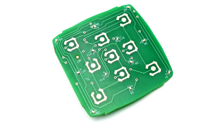
Whether a product is successful or not, first, we should pay attention to the internal quality, and second, we should give consideration to the overall beauty. Only when both are perfect can we consider the product successful.
On a PCB, the Layout of components should be balanced and orderly, and should not be top heavy or heavy.
·Does PCB deform?
·Are process edges reserved?
·Reserve MARK points?
·Do you need a panel?
·How many layers of boards can ensure impedance control, signal shielding, signal integrity, economy and feasibility?
2. Eliminate low-level errors
·Is the size of the printed board consistent with the size of the processing drawing? Can it meet PCB manufacturing process requirements? Are there positioning marks?
·Is there any conflICt between components in 2D and 3D space?
·Are the components arranged in a compact and orderly manner? Is all cloth finished?
·Can components that need to be replaced frequently be easily replaced? Is it convenient to insert the plug-in board into the device?
·Is there a proper distance between the thermal element and the heating element?
·Is it convenient to adjust the adjustable components?
·Are radiators instalLED where heat dissipation is required? Is the air flow unobstructed?
·Is the signal flow smooth and the interconnection shortest?
·Are plugs, sockets, etc. in conflict with mechanical design?
·Is the interference of the line considered?
3. Bypass or decoupling capacitor
During wiring, analog devices and digital devices both need these types of capacitors, and both need to connect a bypass capacitor close to their power supply pins, which is usually 0.1 μ F。 The pin shall be as short as possible to reduce the inductive reactance of the wiring, and shall be as close to the device as possible.
Adding bypass or decoupling capacitors on a circuit board and the arrangement of these capacitors on the board are basic knowledge for digital and analog design, but their functions are different.
In analog wiring design, the bypass capacitor is usually used for high-frequency signals on the bypass power supply. If no bypass capacitor is added, these high-frequency signals may enter the sensitive analog chip through the power supply pin. Generally speaking, the frequency of these high-frequency signals exceeds the ability of the SIMulator to suppress high-frequency signals.
If bypass capacitors are not used in analog circuits, noise may be introduced into the signal path, and even vibration may be caused in more serious cases. For digital devices such as controllers and processors, decoupling capacitors are also required, but for different reasons.
One of the functions of these capacitors is to serve as a "micro" charge bank, because in digital circuits, the switching of the gate state (i.e. switching) usually requires a large current. When switching, the chip generates a switching transient current and flows through the circuit board. It is advantageous to have this additional "standby" charge.
If there is not enough charge when executing the switch action, the power supply voltage will change greatly. If the voltage changes too much, the digital signal level will enter an uncertain state, and it is likely to cause the state machine in the digital device to operate incorrectly.
The switching current flowing through the circuit board wiring will cause the voltage to change. Since the circuit board wiring has parasitic inductance, the following formula can be used to calculate the voltage change:
V=Ldl/dt
Where V=voltage change, L=circuit board wiring inductance, dI=current change through wiring, dt=time of current change.
Therefore, for a variety of reasons, it is a very good practice to apply bypass (or decoupling) capacitors at the power supply or the power pin of the active device.
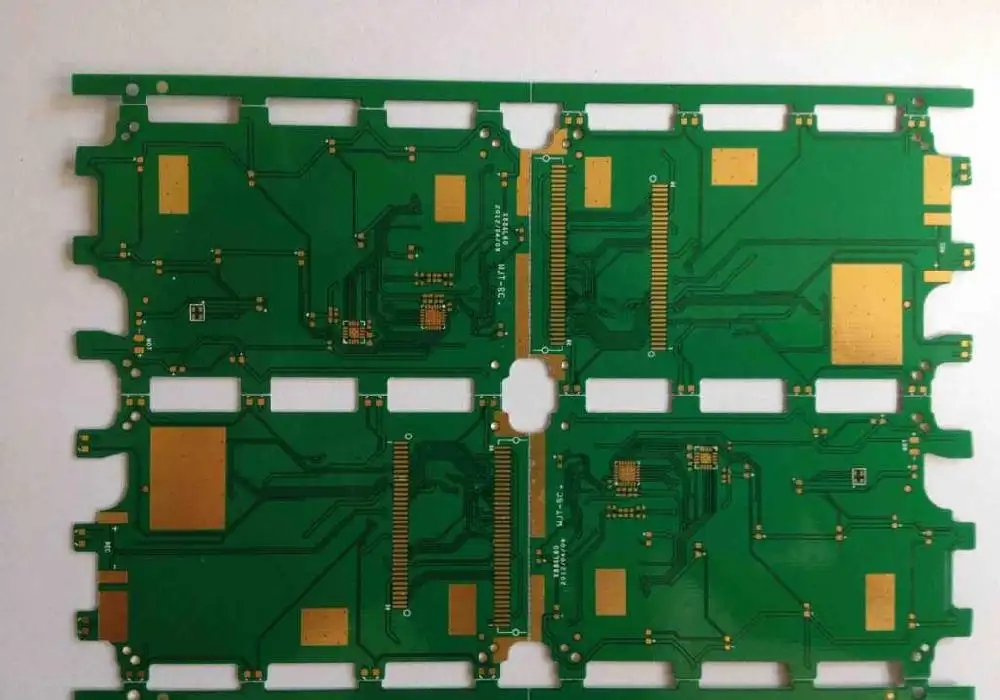
4. If the current of the input power supply is relatively large, it is recommended to reduce the length and area of the wiring, and do not run in full court
The switching noise on the input is coupled to the plane of the power output. The switching noise of the MOS transistor of the output power supply affects the input power supply of the preceding stage.
If there is a large amount of large current DCDC on the circuit board, there will be different frequency, large current and high voltage jump interference.
Therefore, we need to reduce the area of the input power supply to meet the flow. Therefore, in power supply layout, it is necessary to avoid full board running of input power.
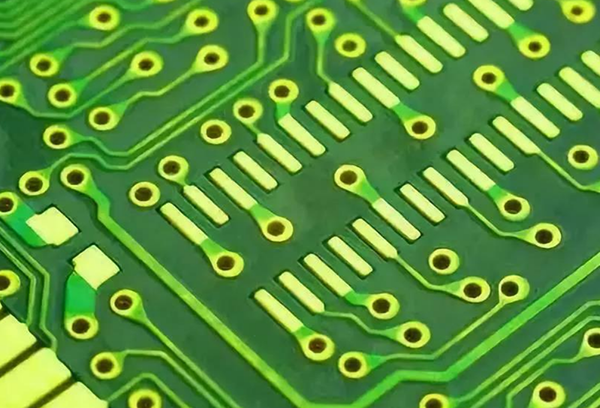
The position of power line and ground wire is well matched, which can reduce the possibility of electromagnetic interference (EMl). If the power cord and ground wire are not matched properly, the system loop will be designed and noise may be generated.
An example of PCB design where the power cord and ground wire are improperly matched is shown in the figure. On this circuit board, different routes are used to lay power lines and ground wires. Due to this improper coordination, electronIC components and circuits of the circuit board are more likely to be subject to electromagnetic interference (EMI).
5. Digital analog separation
In each PCB design, the noise part and "quiet" part (non noise part) of the circuit should be separated.
Generally speaking, digital circuits can tolerate noise interference and are insensitive to noise (because digital circuits have large voltage noise tolerance); On the contrary, the voltage noise tolerance of analog circuits is much SMAller. Among them, analog circuit is most sensitive to switching noise. In the wiring of mixed signal system, these two circuits shall be separated.
6. Thermal considerations
In the layout process, it is necessary to consider the cooling air duct and dead angle; Do not place the thermal sensor behind the heat source wind.
Priority should be given to the layout of users with difficulty in heat dissipation, such as DDR. Avoid repeated adjustment due to failure of thermal simulation.
PCB manufacturers, PCB designers and PCBA manufacturers will explain the important methods of PCB design from a macro perspective.


抖音二維碼

Q Q二維碼

微信二維碼
點擊
然后
聯系
然后
聯系
電話熱線
13410863085Q Q

微信

- 郵箱