鑫景福致力于滿足“快速服務(wù),零缺陷,輔助研發(fā)”PCBA訂購單需求。


PCBA方案設(shè)計(jì)
PCB development and maintenance test method
PCB History
At the beginning of the 20th century, before the advent of printed circuit boards, the interconnection between electronIC components relied on the direct connection of wires to form a complete circuit. In order to SIMplify the production of electronIC equipment, reduce wiring between electronic components, and reduce production costs, people began to study the method of printing instead of wiring.
In 1903, German inventor Albert Hansen described a flat foil conductor with multilayer laminations on insulating plates. Thomas Edison tested the chEMIcal method of electroplating conductors on linen paper in 1904.
In 1913, Arthur Bailey applied for a patent for printing and etching methods in Britain.
In 1927, Charles Ducas of the United States applied for a patent for a method of electroplating circuit patterns.
In 1936, Australian Paul Eisler (Paul Eisler) invented the foil technology in the UK, using a printed circuit board in a radio device Paul Eisler's method is most similar to today's printed circuit boards
In 1941, the mines affected by magnetic fields in Germany used multilayer printed circuits.
In 1943, the United States applied PCB technology to military radios.
In 1948, the United States used PCB printed circuit boards for commercial purposes.
Since the mid 1950s, printed circuit boards have been widely used.
Paul-eisler-by-maurice-hubert-1
Paul Eisler's first radio used a printed circuit chassis and antenna coil
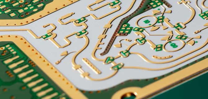
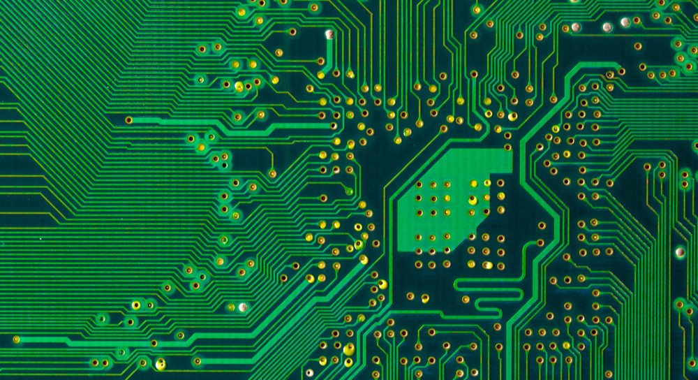
Circuit board

PCB development
printed boards have developed from single-layer to double-sided, multi-layer and flexible, and still maintain their own development trends. Due to the continuous development of high precision, high density and high reliability, the continuous reduction of size, the reduction of cost and the improvement of efficiency, printed circuit boards will remain strong vitality in the future development of electronic equipment.
The discussion on the future development trend of PCB manufacturing technology at home and abroad is basically the same, that is, to develop towards high-density, high-precision, fine aperture, fine wire, fine spacing, high reliability, multi-layer, high-speed transmission, lightweight and thin. In production, it is necessary to improve production efficiency, reduce costs, reduce pollution, and adapt to the development of multi variety and SMAll batch production. The scientific and technological development level of printed circuit is usually expressed by the line width, aperture and thickness/aperture ratio of printed circuit board.
Four Inspection Methods for circuit board maintenance
1. Observation and testing
When checking the circuit board to be repaired, we must first visually inspect its appearance to ensure that it will not cause secondary damage when powered on. If there are general external problems, we can directly see the problems of the circuit board and deal with them.
Human causes
Where the chip is broken or deformed;
Whether the direction of the chip with socket is correct;
Whether the chip socket is forcibly broken;
Check whether the circuit board with short circuit terminal is inserted incorrectly.
Cause of combustion
Whether the resistor, capacitor and diode are burnt out;
Whether the integrated circuit is bulged, cracked, burned or blackened;
Whether the circuit board traces are peeLED off or burnt;
Whether the copper sink hole is out of the bonding pad;
Check whether the fuse and thermistor are burnt out.
2. Static detection
If no problem is found on the circuit board to be repaired through observation and inspection, use a multimeter to measure the main components and troubleshooting points.
Whether the power supply and ground are short circuited
Use a multimeter and a 5V power supply chip to measure the two points on the diagonal and observe whether there is a short circuit.
Does the diode work normally
Use a multimeter to test the positive and negative poles of the diode and observe whether the diode is damaged due to excessive current.
Whether the capacitor is short circuited or open circuited
Measure the capacitance with a multimeter to see if there is a short circuit or open circuit. If yes, check whether there is a problem with the component itself or the connected circuit.
Whether the component meets the logic efficiency
Use a multimeter to test the integrated circuit, transistor, resistance, etc., and check the resistance line of the busbar structure.
3. On site inspection
It is mainly used for PCB manufacturers. Manufacturers usually use a general debugging platform to test circuit boards, subdivide problems through observation and static testing, and finally lock the components with problems. If the problem is not solved, it needs to be checked through real-time detection.
Are the components overheating
Power on the circuit board and check whether the temperature of each chip is normal. If the temperature is too high, replace it and check whether it is normal.
Whether PCB door circuit conforms to logic relationship
Use an oscilloscope to measure the grid circuit of the circuit board, the output is low, the measurement is high, and the chip is damaged; The output is high, the measurement is low, the connection between the chip and the circuit is disconnected, and the measurement logic is reasonable.
Whether crystal oscillator of digital circuit has output
Use an oscilloscope to measure whether the crystal oscillator has an output, and then remove the connected chip for judgment. There is still no output, and the crystal oscillator is damaged; If there is an output, install and test the connected chips in turn.
Whether the digital circuit is normal
Use an oscilloscope to measure the digital circuit with busbar structure and observe whether the model is normal.
4. Online test
Check the problem circuit board by comparing their advantages and disadvantages
The above is the explanation given by the editor of pcb circuit board company.
If you want to know more about PCBA, you can go to our company's home page to learn about it.
In addition, our company also sells various circuit boards,
High Frequency Circuit Board and SMT chip are waiting for your presence again.


抖音二維碼

Q Q二維碼

微信二維碼
點(diǎn)擊
然后
聯(lián)系
然后
聯(lián)系
電話熱線
13410863085Q Q

微信

- 郵箱