鑫景福致力于滿足“快速服務,零缺陷,輔助研發”PCBA訂購單需求。


PCBA方案設計
PCB production method is always suitable for you
Production method I:
1. Cut the copper clad plate to the size required by the circuit diagram.
2 Put the wax paper on the steel plate, use a pen to carve the circuit diagram on the wax paper in 1:1 ratio, cut and carve the circuit diagram on the wax paper PCB according to the size, and then put the cut wax paper on the printed copper plate Take a SMAll amount of paint and talcum powder to make a suitable thin and thICk printed material. DIP the printed material with a brush and evenly SMEar it on the wax paper. Repeat several tiMES. The circuit can be printed on the printed board This prototype can be reused and suitable for small batch production
3. Use 1 g potassium chlorate and 40 ml 15% hydrochloric acid to prepare the corrosion solution and apply it to the corrosion area on the PCB for corrosion.
4. Clean the corroded printed board repeatedly with water. Wipe off the paint with banana water, and then clean the printed board several times to make it clean without leaving corrosive liquid. Before drilling, apply a layer of rosin solution and dry it.
Production method II:
There are many ways to make printed boards in amateur conditions, but they are either time-consuming, complex, or of poor quality. My method of making printing plate is one of the methods with better comprehensive effect, as follows:
1. Make printed board map. The pads in the figure are represented by dots. The connection can be a single line, but the location and size must be accurate.
2. Cut the printed board according to the drawing size of the printed board and clean the copper foil surface.
3. Use carbon paper to copy the chart onto the printed board. If the circuit is SIMple and the manufacturer has some experience in board making, this step can be omitted.
4. Paste standard pre cut symbols (pads) with different inner and outer diameters according to the actual conditions of the components; Then paste tape lines of different widths according to the current. The electronic store provides standard pre cut symbols and tapes. Common specifications of pre cutting symbols include D373 (0D-2.79, ID-0.79), D266 (0D-2.00, ID-0.80), D237 (OD-3.50, ID-1.50), etc. It is better to purchase paper materials. (Black), plastic based (red) materials should not be used as much as possible. Common specifications of tape are 0.3, 0.9, 1.8, 2.3, 3.7, etc. All tissues are mm.
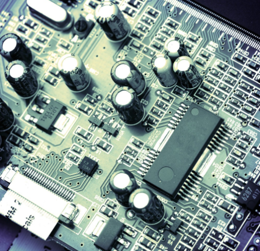
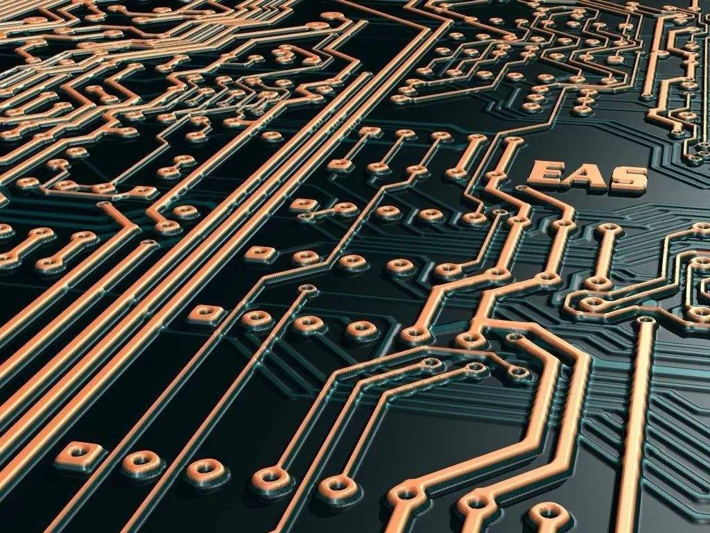
circuit board

5. Knock the sticker with a soft hammer, such as smooth rubber and plastic, to make it completely adhere to the copper foil. Focus on turning and overlapping of lines. In cold weather, it is best to use a heater to heat the surface to enhance adhesion.
6. Put it into 3 ferric chloride for corrosion, but pay attention that the liquid temperature is not higher than 40 ℃. After corrosion, it shall be taken out and washed in time, especially when there are fine lines.
Hit your eyes, polish the copper foil with fine sandpaper, coat it with rosin alcohol solution, and let it dry. The quality of this kind of PCB is very close to that of ordinary pcb. The 0.3mm adhesive tape can pass between the pins of the integrated circuit, which can greatly reduce the short circuit on the front of the circuit board, thus saving trouble and time. In my work, I often use this method to make experimental plates or a small number of products.
Production method 3:
Dissolve one part of paint (i.e. lac, which can be bought in chEMIcal raw material stores) in 3 parts of anhydrous alcohol, and mix properly. It is of a certain color and can be used as the protective paint of PCB after being mixed evenly.
First polish the copper clad laminate with fine sandpaper, and then draw with the duckbill in the drawing tool (or the ink duckbill used to draw figures on the compass). The duckbill pen has a nut to adjust the thickness of the stroke. The thickness of the stroke can be adjusted. You can use a ruler or a three square to draw a very thin line. The line drawn is smooth and even, without edge serrations, giving a smooth feeling; At the same time, it can also be in the free position of the pcb board. Write Chinese characters, English, Pinyin or symbols.
If the drawn line penetrates into the surroundings and the concentration is too small, you can add a little paint flake; If you can't draw a brush, it's too thick. You need to drop a few drops of absolute alcohol. Just use a small wooden stick (match stick) to make a small cotton swab, dip it in a little absolute alcohol, you can easily wipe it clean, and then draw it again. After drawing the circuit board diagram, the circuit board may be corroded in 3 ferric chloride solution. It is also convenient to remove the paint after the circuit board is corroded. Wipe off the protective paint with anhydrous alcohol dipped in a cotton ball, dry it for a while, and then apply pine perfume.
Since the alcohol evaporates quickly, the prepared protective paint should be seaLED and stored in a small bottle (such as an ink bottle). Don't forget to cover the bottle after use. If the concentration becomes thicker when next used, just add an appropriate amount of absolute alcohol.
Production method IV:
Paste the note on the copper foil of the copper clad plate, then draw the circuit on the single board, and then use the cutting machine to cut on the single board to form the required circuit, remove the non circuit part, and finally use the ferric chloride corrosion or current electrolysis method to produce a more ideal pcb circuit board
The corrosion temperature can be about 55 ℃, and the corrosion rate is faster. Rinse the Corroded circuit board with clean water, remove the adhesive on the circuit, make a hole, wipe it clean, and then apply rosin alcohol solution for use.
Production method V:
1. According to the shape of the components used in the project, reasonably arrange the density of the components and the location of each component PCB schematic diagram and printed board area size The position of components shall be determined according to the principle of "large first, small second", and then small, first as a whole, then as a part, so that adjacent components in the circuit can be placed nearby and arranged neatly and evenly
2. Connecting lines between components shall not rotate at right angles at corners and intersections of two lines. They must be transited through curves and shall not cross each other or rotate too far. When some wires cannot do this, you can consider printing wires on the back of the printed board, and then using studs to connect with the front circuit, or using insulated wires when welding components.
3. The input part and the output part should be separated further to avoid mutual interference.
The above is the explanation given by the editor of pcb circuit board company.
If you want to know more about PCBA, you can go to our company's home page to learn about it.
In addition, our company also sells various circuit boards,
High Frequency Circuit Board and SMT chip are waiting for your presence again.


抖音二維碼

Q Q二維碼

微信二維碼
點擊
然后
聯系
然后
聯系
電話熱線
13410863085Q Q

微信

- 郵箱