鑫景福致力于滿足“快速服務,零缺陷,輔助研發(fā)”PCBA訂購單需求。


PCBA方案設計
Two main points of PCB layout and wiring
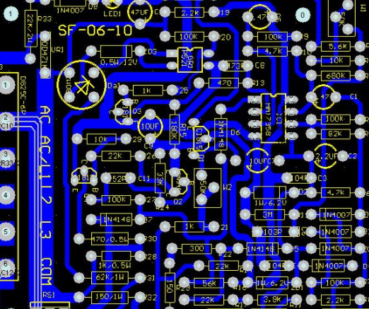
PCB circuit board is also calLED printed circuit board (printed circuit board), whICh can realize circuit connection and function realization between electronIC components. It is also an important part of power circuit design
1. Basic rules of component layout
1. Relevant circuits that are laid out according to circuit modules to achieve the same function are called modules. The components in the circuit module shall be centralized nearby, and the digital circuit and analog circuit shall be separated;
2. No components or devices shall be installed within 1.27mm around non installation holes such as positioning holes and standard holes, and 3.5mm (M2.5) and 4mm (M3) components shall not be installed around installation holes such as screws;
3. Avoid placing through holes under resistors, inductors
4. The outer side of the component is 5mm from the edge of the plate;
5. The distance between the outside of the mounting element pad and the outside of the adjacent inserted element is greater than 2mm;
6. The metal shell assembly and metal parts (mask box, etc.) shall not contact with other components, and shall not be close to the printed line and bonding pad. The distance between them shall be greater than 2mm. The square holes such as positioning holes, fastener mounting holes and elliptical holes on the plate are larger than 3mm from the edge of the plate;
7. The heating element shall not be close to the conductor and thermal sensor; High heating devices shall be evenly distributed;
8. The power socket shall be arranged around the printed board as much as possible, and the power socket and the bus terminal connected to it shall be arranged on the same side. Special attention shall be paid not to arrange power sockets and other welding connectors between connectors, so as to facilitate the welding of these sockets and connectors, and the design and binding of power cables. The spacing between power sockets and welding joints shall be arranged to facilitate the plugging and unplugging of power plugs;
Circuit board

9. Arrangement of other components:
All IC components are aligned on one side, and the polarity MARKs of polar components are clear. The polarity of the same printed board cannot be marked in more than two directions. When there are two directions, the two directions are perpendicular to each other;
10. Panel wiring shall be dense. When the density difference is too large, MESh copper foil shall be filled, and the mesh shall be greater than 8mil (or 0.2mm);
11. There should be no through hole PCB patch pad on the panel to avoid loss of solder paste and lead to false welding of components Important signal lines are not allowed to pass through the socket pins;
12. One side of the patch shall be aligned with the same character direction and packaging direction;
13. Polarization equipment shall be as consistent as possible in the direction of polarity marks on the same circuit board.
2、 Component wiring rules
1. Draw the PCB board in the wiring area within 1mm from the edge of the cable, and prohibit wiring within 1mm around the mounting hole;
2. The power cord shall be as wide as possible and not less than 18mil; The signal line width shall not be less than 12 mils; CPU input and output lines shall not be less than 10mil (or 8mil); The line spacing shall not be less than 10mil;
3. Normal through-hole is not less than 30mil;
4. Double in-line type: 60ml pad, 40ml aperture; 1/4W resistance: 51 * 55mil (0805 surface mount); 62mil pad, 42mil aperture in series; Infinite capacitor: 51 * 55mil (0805 surface mount); In series connection, pad is 50 mil and aperture is 28 mil;
5. Note that the power line and ground wire should be radial as far as possible, and the signal line should not be annular.
How to improve anti-interference ability and electromagnetic compatibility?
How to improve anti-interference ability and electromagnetic compatibility when developing electronic products with processors?
The following systems shall pay special attention to anti electromagnetic interference:
(1) The utility model relates to a system with extremely high clock frequency of a microcontroller and extremely fast bus cycle.
(2) The system includes high power and high current driving circuits, such as spark generation relay, high current switch, etc.
(3) A system comprising a weak analog signal circuit and a high-precision analog to digital conversion circuit.
The above is the explanation given by the editor of pcb circuit board company.
If you want to know more about PCBA, you can go to our company's home page to learn about it.
In addition, our company also sells various circuit boards,
High Frequency Circuit Board and SMT chip are waiting for your presence again.

Ground treatment PCB surface technology
11-17,2022


抖音二維碼

Q Q二維碼

微信二維碼
點擊
然后
聯(lián)系
然后
聯(lián)系
電話熱線
13410863085Q Q

微信

- 郵箱