鑫景福致力于滿足“快速服務(wù),零缺陷,輔助研發(fā)”PCBA訂購(gòu)單需求。


PCBA方案設(shè)計(jì)
Parallel design Strategy of High Speed PCB and Hole Size of Pad
PCB manufacturers, PCB designers and PCBA manufacturers will explain the parallel design strategy of high-Speed PCB and the aperture size of pads
Based on the overall process analysis of PCB design, it can be roughly divided into the following stages: netlist import, packaging and database building, master design, physICal and electrical constraint design, layout, wiring, design review, and design output. For a complex design, from the perspective of the task itself, the layout and wiring are relatively heavy, especially the wiring. From the long-term experience, the manual wiring of important signals is still the main form of wiring.
Considering the complexity and arduousness of the layout and routing task process, the concurrent design method is considered. The parallel design methods for layout and routing are basically SIMilar, with different objectives and priorities. The layout is taken as an example to describe the special points of parallel routing design.
Task analysis and decomposition
The starting point of layout analysis is structural design constraints and circuit topology analysis. Structural design constraints include border shape and size requirements, positioning and height limit requirements of mounting holes and special components, regional use constraints, etc.
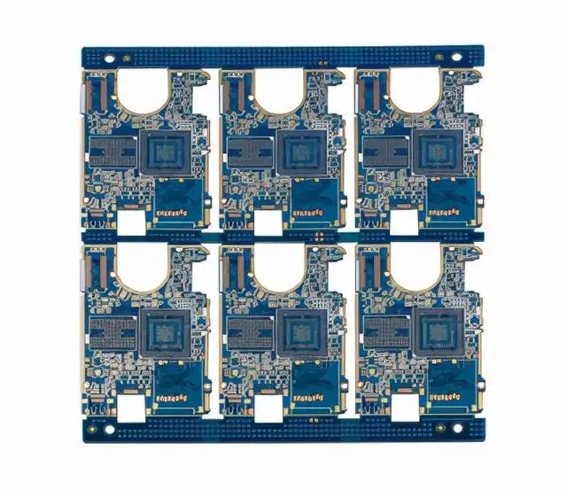
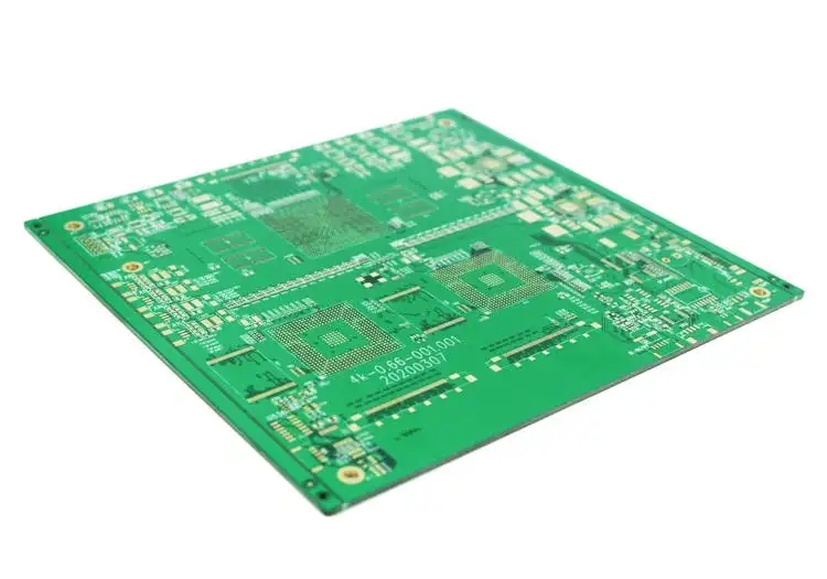
Consider a typical design example, taking the design of mobile phone board as an example. From the view of circuit topology, the signal characteristics of each part have obvious differences in the requirements for layout. The layout of each component will be carried out according to the signal flow, and shielding, electromagnetic compatibility (EMC) and other design requirements shall be taken into account. For the sake of product reliability and stability, signal integrity (SI) should also be considered.
Through the analysis of the above typical design examples, we can get a method of parallel design layout: expand the circuit topology type, plan appropriate space for each component, and arrange appropriate engineers for parallel design layout.
Role arrangement
Consider the following task decomposition of concurrent design layout:
1. Communication protocol related groups, including RF components (power amplifier/transceiver/frequency converter, etc.), analog digital hybrid components, conventional analog/logIC components, digital baseband processors, etc;
2. Application related group, including LCD/backlight driver, image processing engine, application processor, memory (RAM), flash memory (Flash), storage (SDCard), etc;
3. Public signal related groups, including interfaces, power supply and power management, clock components, etc.
It is assumed that each of these parallel phases is performed and completed by an engineer. The following roles are assigned: Engineer A is responsible for layout design and communication protocol group layout; Engineer B is responsible for applying relevant group layout; Engineer C is responsible for the layout of public signal related groups. The principle of role arrangement is to focus on the skills and specialties of each engineer.
Layout concurrent design
Wherein, Engineer A completes the main design (the staged design document that guides the design of the net list, structural constraints, and installation holes have been positioned), plans the sub layout material labels according to the above decomposition method, and allocates the layout intervals according to the design requirements, and prepares the task allocation instruction document; Engineer A divided the power generation principle design drawing, bill of materials, task allocation description document, PCB main design document, etc. to the other two engineers.
Each engineer (including Engineer A) shall carry out the layout according to their own layout area and relevant requirements. After the completion of the layout, components irrelevant to their own tasks shall be deleted. Export respective sub layout files through PCB tool software and submit them to responsible engineer A.
After receiving each sub layout file, Engineer A still imports the sub layout file to its own sub layout file in turn through PCB tool software. Engineer A adjusts and optimizes the layout according to the design requirements.
Concurrent Design of Cabling
The starting point of wiring analysis is generally circuit topology power on signal analysis. Electrical signals can be divided into two categories: critical signals (signals with strict electrical constraints) and non critical signals.
Still considering the aforementioned design examples of mobile phone boards, the requirements for wiring in each part are obviously different. The wiring of each component still needs to be carried out according to the layout elements and signal flow, while taking into account the electrical performance design requirements.
For the above typical design examples, the following parallel design routing method can be considered: the routing priority can be determined based on the circuit topology type (i.e. required area division) and signal flow. For those with high routing priority (often with heavy workload), priority shall be given to routing to ensure performance and progress.
It can be considered to assign concurrent design tasks in high priority cabling tasks, and then the responsible engineer will improve and organize them later. In addition, the use of tools is different from that in the layout stage. The sub design files will be exported and imported in the routing stage.
Summary
This paper describes the method of concurrent design through the principle analysis of a mobile phone Board Design example, and realizes the operation of concurrent design through the combination of task division and tools, which not only achieves the complementary advantages of resources, but also ensures the design quality and schedule requirements.
Hole size of bonding pad shall be considered in PCB design
The design according to the requirements of the pad is to achieve a SMAll diameter, which is at least 0.5mm larger than the large diameter of the small hole flange of the welding terminal Test pads must be provided for all nodes according to ANSI/IPC 2221. Nodes refer to electrical connection points between two or more components A test pad requires a signal name (node signal name), x-y coordinate axis related to the reference point of the printed circuit board, and the coordinate position of the test pad (indicating which side of the printed circuit board the test pad is located on) It is necessary to provide SMT with the data of fixed devices, and also need the temperature closing technology of PCB assembly layout to promote the testability in the circuit with the help of the "fixed device for circuit test" or commonly referred to as the "nail bed fixed device". To achieve this goal, it is necessary to:
1) The diameter of the test pad specially used for detection shall not be less than 0.9mm.
2) The space around the test pad shall be greater than 0.6mm but less than 5mm. If the height of the component is greater than 6.7 mm, the test pad shall be placed 5 mm away from the component.
3) Do not place any components or test pads within 3mm from the edge of the printed circuit board.
4) The test pad shall be placed in the center of a 2.5mm hole in a grid. Where possible, standard probes and a more reliable fixture are permitted.
5) Do not rely on the edge of the connector pointer for pad testing. The test probe can easily damage the gold plated pointer.
6) Avoid plated through holes - probe both sides of the printed circuit board. Place the test pass hole on the non component/welding surface of the printed circuit board. PCB manufacturers, PCB designers and PCBA manufacturers will explain the parallel design strategy of high-speed PCB and the aperture size of pads.


抖音二維碼

Q Q二維碼

微信二維碼
點(diǎn)擊
然后
聯(lián)系
然后
聯(lián)系
電話熱線
13410863085Q Q

微信

- 郵箱