鑫景福致力于滿足“快速服務,零缺陷,輔助研發”PCBA訂購單需求。


PCBA方案設計
The default value of single ended PCB is 50 ohms for control
Many people who are new to impedance will have this problem Why is a common single ended trace PCB controlLED by 50 ohms instead of the default 40 ohms or 60 ohms? This is a seEMIngly SIMple question that is not easy to answer Before writing this artICle, we also looked up a lot of information, the most famous of which is Howard Johnson, who answered this question,
Why is it difficult to answer? The signal integrity problem itself is a tradeoff problem. Recall that the most famous sentence in the industry is: "It depends on..." This is a question without a standard answer. Today, Mr. Expressway will briefly summarize this question with various answers. Here is also an introduction. I hope more people can summarize more relevant factors from their own perspective.
First of all, 50 ohms has a certain historical origin, which must start with standard cables. As we all know, a large part of modern electronic technology originates from the military, and has gradually changed from military use to civilian use. In the early days of microwave application, that is, during the Second World War, the selection of impedance was completely determined by the use demand. With the development of science and technology, it is necessary to establish impedance standards in order to achieve a balance between economy and convenience. In the United States, the most commonly used conduit is connected by existing rods and water pipes. 51.5 ohms is very common, but the adapters/converters seen and used are 50 ohms to 51.5 ohms; This is a joint Army and Navy solution. To solve these problems, an organization called JAN was established, which was later called DESC and was developed by MIL professionally. After comprehensive consideration, 50 ohm is finally selected to manufacture special conduits and convert them into various cables. At that time, the European standard was 60 ohms. Soon after, under the influence of Hewlett Packard and other companies leading the industry, Europeans were forced to change, and finally 50 ohms beCAMe the standard of the industry.
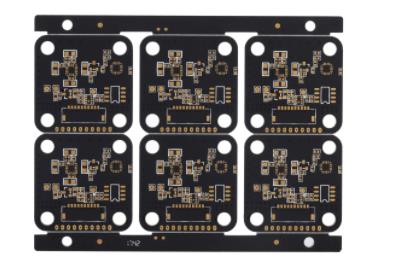
Circuit board

It has become a convention that printed circuit boards connected to various cables eventually need to meet the impedance matching 50 ohm impedance standard
Secondly, from the perspective of PCB production, 50 ohms is more convenient. It can be seen from the impedance calculation formula above that too low impedance requires wider linewidth and thinner medium (or greater dielectric constant), which is more difficult to meet in space for current high-density plates; High impedance requires high thin line width and thicker dielectric (or SMAller dielectric constant), which is unfavorable to suppress electromagnetic interference and crosstalk. At the same time, from the perspective of mass production, the reliability of Multilayer board processing will be relatively poor; It is not surprising that the 50 ohm common line width and dielectric thickness (4~6mil) meet the design requirements in the environment of common data (impedance calculation is shown in the figure below) and are easy to handle.
Third, from the perspective of loss, based on basic physics, it can be proved that 50 ohm impedance skin effect has the smallest loss (from the reply of Dr. Howard Johnson). In general, the skin effect loss (dB) of cable L is proportional to the total skin effect resistance R (tissue length) divided by the characteristic impedance Z0. The total skin effect resistance R is the sum of the resistance of the mask layer and the intermediate conductor. At high frequencies, the skin effect resistance of the mask layer is inversely proportional to its diameter d2. The skin effect resistance of the inner conductor of a coaxial cable is inversely proportional to its diameter d1 at high frequencies. In this case, the total series resistance R is proportional to (1/d2+1/d1). Combining these factors, given the corresponding dielectric constant Er of d2 and isolation data, the following formula can be used to minimize the skin effect loss.
In any basic book on electromagnetic field and microwave, you can find that Z0 is a function of d2, d1 and Er.
Substitute Formula 2 into Formula 1, and multiply the numerator and denominator by d2 to get
Separate the constant term (/60) * (1/d2) and the effective term ((1+d2/d1)/ln (d2/d1)) from Equation 3 to determine the minimum point. Carefully observe the minimum point of Formula 3 controlled only by d2/d1, which is independent of Er and the fixed value d2. With d2/d1 as the parameter, draw the graph of L. When d2/d1=3.5911, the minimum value is obtained. Assume that the dielectric constant of solid polyethylene is 2.25, d2/d1=3.5911, and the characteristic impedance is 51.1 ohms. A long time ago, radio engineers, for convenience, approximated this value to 50 ohms as the best value for coaxial cables. This proves that L is the smallest at about 50 ohms.
Finally, from the perspective of power efficiency, after comprehensive consideration, the advantage of 50 ohms is also a compromise It is purely because of PCB track, low impedance is better For a transmission line with a given line width, the closer it is to the aircraft, the less electromagnetic interference and crosstalk will be, and it will not be easily affected by capacitive loads Impact However, from the perspective of the complete path, the most critical factor to consider is the drive capability of the chip In the early days, most chips could not drive transmission lines with impedance lower than 50 ohms, and transmission lines with higher impedance were inconvenient to implement A 50 ohm impedance is used for
To sum up: 50 ohms has its inherent advantages as a PCB industry, which is also a compromise after comprehensive consideration, but it does not mean that 50 ohms must be used In many cases, it depends on matching For example, 75 ohms is still the standard for remote communication Some cables and antennas use 75 ohms At this time, matching PCB line impedance is required In addition, some special chips can reduce the impedance of the transmission line by improving the driving ability of the chip, so as to better suppress electromagnetic interference and crosstalk For example, most Intel chips require 37 ohms of impedance control, 42 ohms or less I won't repeat it here


抖音二維碼

Q Q二維碼

微信二維碼
點擊
然后
聯系
然后
聯系
電話熱線
13410863085Q Q

微信

- 郵箱