鑫景福致力于滿足“快速服務(wù),零缺陷,輔助研發(fā)”PCBA訂購(gòu)單需求。


PCBA方案設(shè)計(jì)
Precautions for PCB copper wiring
Line current density: Most electronIC circuits now consist of copper connected by insulating plates. The copper sheet thickness of ordinary circuit board is 35mM, and the current density value can be obtained according to the experience value of 1A/M, and the specific calculation can refer to the textbook. The line width should be greater than or equal to 0.3mm to ensure the mechanical strength of the wiring (the line width of other non power circuit boards may be SMAller). The circuit board with a copper sheet thickness of 70mM is also common in switching power supply, and the current density can be higher.
In addition, the commonly used PCB design tool software generally has design specifications, such as line width, line spacing, drying tray hole size and other parameters can be set. When designing the circuit board, the design software can be automatically executed according to the specification, which can save a lot of time, reduce part of the workload and reduce the error rate.
In general, double-sided boards can be used for circuits with high reliability or high wire density. It has the characteristics of moderate cost and high reliability, and can meet most applications.
There are also some products with multilayer boards in the power cord of the module, which are mainly used to integrate transformer inductance and other power equipment, optimize wiring, power tube cooling, etc. It has the advantages of good processability, good consistency and good heat dissipation of transformer, but its disadvantages are high cost and poor flexibility, and it is only suitable for large-scale industrial production.
Single board and MARKet circulating general switching power supply almost all use single side circuit board, which has the advantage of low cost. Some measures have been taken in the design and production process to ensure its efficiency.

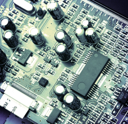
Today we will talk about some experiences in the design of single-sided printed circuit boards. Single sided printed circuit boards are widely used in switching power lines because of their low cost and ease of manufacture. Since only one side of the device is combined with copper, the electrical connection and mechanical fixation of the device depend on the copper layer, so care must be taken during handling.
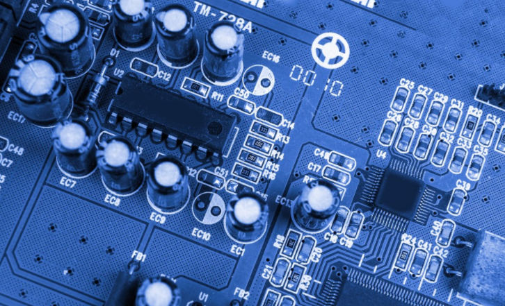
printed circuit board
In order to ensure the good structural efficiency of the welding machine, the single board pad should be slightly larger to ensure a good bonding force between the copper sheet and the substrate, and the copper sheet will not peel and break when subjected to vibration. In general, the width of the welding ring should be greater than 0.3mm. The diameter of the pad hole should be slightly larger than the pin diameter of the device, but not too large. Make sure that the distance between the pin and the gasket is short, and the dimension of the gasket hole should not hinder the normal inspection. The diameter of the pad hole is usually 0.1-0.2mm larger than the diameter of the pin. The multi needle device can be larger to ensure smooth inspection.
The power connection shall be as wide as possible, and the principle width shall be greater than the pad diameter. In special cases, when connecting to the pad, the line must be widened (usually calLED tearing) to avoid disconnection between the line and the pad under certain conditions. The main line width shall be greater than 0.5mm.
components on individual panels shall be tightly connected to the circuit board. For components requiring overhead heat dissipation, adding sleeves on the pins between the components and the circuit board can play a dual role in supporting the components and adding insulation, minimizing or avoiding the impact of external forces on the bonding pad to pin connection, and improving the welding fastness. Heavy parts on the circuit board can add support connection points and enhance the connection strength with the circuit board, such as transformers and power equipment radiators.
The pins on the welding surface of the veneer can be retained for a longer time without affecting the distance between the shells. Its advantage is to increase the strength of the welding area, increase the welding area, and detect the virtual welding phenomenon in real time. When the pin is long enough to cut the leg, the force on the weldment is small. In Taiwan and Japan, the process of bending the pins of the equipment on the welding surface to a 45 degree angle with the circuit board is usually used before welding, which is also the same reason. Today, I will talk about some problems in double-sided Board Design. In some application environments with high requirements or high wire density, double-sided PCBs are far superior to single boards in terms of performance and number of seats.
Since the hole has been metallized to a higher strength, this ring can be smaller than the ring of a single plate, while the hole diameter of a double plate can be slightly larger than the hole diameter of a pin, because during welding, the tin solution is conducive to penetrating the hole into the top layer of the pad, so as to improve the reliability of welding. However, there is also a disadvantage. If the hole is too large, some parts of the equipment may float under the influence of tin spraying during peak welding, which may lead to some defects.
For the processing of high current lines, the line width can be processed according to the previous one. If the width is not enough, the tinned wire can be used to increase the thickness. There are many ways to solve this problem.
1. Set the path as the pad content, so that it will not be covered by solder during PCB manufacturing, and it will be tinned during thermal air conditioning.
2. Place pads in the wire connection and set pads to the desired shape. Carefully set the pad hole to zero.
3. This method is flexible when placing wires in a solder mask, but not all circuit board manufacturers will understand your intentions and need to record them. Solder shall not be used where the conductor is placed on the cable
Solder layer
As mentioned above, it should be noted that if the wide wire is completely tinned, a large amount of solder will be bonded after welding, and the distribution is very uneven, which will affect the appearance. Generally, a long and thin tin strip with a width of 1~1.5mm can be used, and the length can be determined according to the line. The double-sided circuit board with a distance of 0.5~1mm between tin plated parts provides a great choice for layout and wiring, making the wiring more reasonable. As for grounding, power grounding must be separated from signal grounding. The two grounds can be connected at the filter capacitor to avoid unexpected factors that may cause instability when connecting large pulse current through signal connection. Point grounding method shall be used for signal control circuit as far as possible. There is a technology that attempts to place ungrounded wires in the same wiring layer and ground wires on another layer. Usually, the output line passes through the filter capacitor before reaching the load, and the input line must pass through the capacitor before reaching the transformer. The theoretical basis is that the ripple current passes through the filter capacitor.
Voltage reverberation sampling: in order to avoid the influence of large current passing through the line, the sampling point of the reverberation voltage must be placed at the power output terminal to improve the load effect quota of the whole unit.
The wiring from one wiring layer to another is usually connected through holes, which is not suitable for passing through the pin pad of equipment, because this connection may be broken when inserting equipment, and there should be at least two holes for every 1A current. The principle of hole size shall be greater than 0.5mm, generally 0.8mm, to ensure the reliability of processing.
Device heat dissipation. In some small power supplies, the wiring of the circuit board can also have the heat dissipation function. Its feature is that the wiring is as wide as possible to increase the heat dissipation area, and no solder is used. Conditionally, holes can be placed evenly to improve thermal conductivity.


抖音二維碼

Q Q二維碼

微信二維碼
點(diǎn)擊
然后
聯(lián)系
然后
聯(lián)系
電話熱線
13410863085Q Q

微信

- 郵箱