鑫景福致力于滿足“快速服務,零缺陷,輔助研發”PCBA訂購單需求。


PCBA方案設計
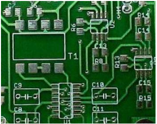
Construction and characteristICs of capacitors in pcb design
When a potential is applied to the conductor, the PCB conductor will be charged. However, with respect to the same potential, the number of charges contained by a conductor varies with its own structure. The ability of conductor to contain electric charge is calLED capacitance of PCB design. Generally, the charge Q (coulomb) contained by a conductor is proportional to its potential V (volt, relative to the earth), that is, there is
C is the designed electrical capacity of the PCB of the conductor. The unit of capacitance designed by PCB is farad (F).
An insulating medium is inserted between two parallel metal plates, and the lead electrode becoMES a capacitor for PCB design. Its circuit symbols are capacitors designed with polar pcb and capacitors designed with nonpolar PCB.
If the capacitor designed by pcb is charged, the charge will accumulate on the bipolar plates of the capacitor designed by pcb. The capacitor designed for pcb with capacitance of C is charged with constant current intensity I. It is assumed that the capacitor designed by pcb is initially free of charge, that is, the initial voltage at both ends of the capacitor is equal to zero. We recall the definition of current: the charge moves in the conductor to form the current. The amount of charge flowing through the conductor cross section in unit time is called the current intensity. That is, there is, and because there is, in the capacitor designed by the pcb, so.
That is, under the action of constant current intensity I, the voltage V at both ends of a PCB designed capacitor with a capacitance of C increases linearly with time t.
The higher the voltage at both ends of the capacitor designed by pcb, the more charge it contains, that is, the greater the energy storage. However, the dielectric strength between the two plates of the capacitor designed by PCB is limited. If the electric field strength between the two plates of the PCB is too high, the dielectric may be broken down, thus making the capacitor designed by PCB short circuited. Therefore, the withstand voltage of capacitor designed by pcb should be coordinated in application.
Conclusion: the capacitor designed by pcb has the function of containing charge in the circuit, that is, storing energy. The storage energy of pcb capacitor needs time, so the voltage at both ends of pcb capacitor can not change suddenly. And the larger the capacitance of pcb design, the more energy can be stored. The two most important parameters of pcb designed capacitor are its pcb designed capacitance and withstand voltage.
2. RC charging and discharging circuit
The circuit is represented by an RC charging and discharging circuit. Assume that the initial voltage at both ends of the capacitor designed by the pcb is zero, and the power supply charges the capacitor designed by the pcb through the resistance R when the switch K and the end 1 are connected. At this time, the charging current of the capacitor designed by the pcb is the maximum E/R. If the current continues to charge, the rising curve of VC is a linear straight line.
However, since the charging current is during the whole charging process, with the increase of VC, the charging current strength IC gradually decreases, so the increase of VC gradually decreases until it reaches the power supply voltage E, and the charging current is 0. This makes the VC rising curve of practice. VC rises according to the exponential law, and the expression of its change with time t is:
Where, is the time constant.
It can be seen that the larger the series resistance R is, the SMAller the charging current is, and the longer the charging time is; The larger the capacitance C of the pcb design, the more charge required (i.e., the more energy stored), and the longer the charging time.
When the capacitor designed by the pcb is charged, VC is equal to E. At this time, the switch K is connected to the 2 terminals, and the capacitor designed by pcb discharges through R, the discharge current is, and VC gradually decreases. At the moment when the 2 terminals are connected, the discharge current is the maximum, but with the decrease of VC, the discharge current also gradually decreases until VC is 0V, and the discharge current is also 0. Thus, the falling curve of VC during capacitor discharge of pcb design.
3. Capacitance reactance of pcb designed capacitor
The capacitance designed by pcb has a very important role in the circuit, which is to connect ac and isolate dc. If a DC voltage is applied to one end of the capacitor designed by the pcb, after the capacitor designed by the pcb is stabilized (i.e., after the charging and discharging process is completed), the voltage cannot be felt at the other end of the capacitor designed by the pcb, that is, the DC is separated, as can be seen from the RC charging and discharging circuit; If the input Vi is an AC signal, Vo will output an AC signal of the same frequency, and the higher the input AC signal frequency, the greater the amplitude of the output Vo, that is, the AC signal passes through the capacitance designed by this circuit board.
In fact, we can understand that the amplitude and direction of the AC signal change with time, and the response of the capacitor designed by the pcb to the voltage is Sui, that is, the voltage at its two ends cannot change suddenly. When the potential of one electrode plate of the capacitor designed by pcb changes rapidly with the input signal, and the voltage at both ends of the capacitor designed by pcb changes slowly, the potential of the other electrode plate that causes it changes in the same way. In this way, although there are some losses (after all, the voltage at both ends of the capacitor designed by the pcb has changed a little), it is also equivalent to the AC signal passing through the capacitor designed by the pcb. Moreover, the faster the input signal changes (i.e., the higher the frequency), the larger the capacity of the capacitor designed by the pcb (i.e., the slower the voltage changes at its two ends), and the easier it will pass through.
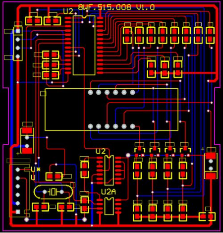
pcb design
4. Filtering function of capacitor designed by pcb
Using the characteristics of capacitors designed by pcb, we can make filters. The circuit is a high pass filter, that is, the higher the frequency of the input signal, the easier it is to pass through, and the lower the frequency, the harder it is to pass through, and DC is not allowed to pass through, so that the low-frequency component in the signal can be filtered out. On the contrary, the circuit is a low-pass filter, which can filter out the high-frequency components of the signal.
(a) High pass filter (b) Low pass filter
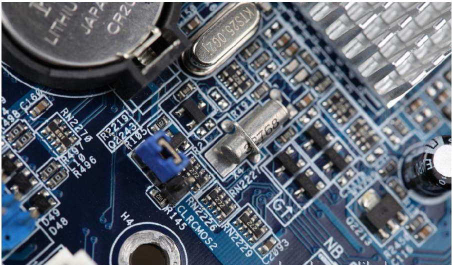
5. Classification of capacitors commonly used in pcb design
The capacitance of pcb design should be carefully selected. Generally, well-known pcb design capacitor brands can be selected, such as TDKpcb design capacitor, Guoju pcb design capacitor, etc., as quality assurance.
(1) Capacitance of pcb design for aluminum electrolysis
The capacitor designed for aluminum electrolytic pcb is a capacitor designed for polar pcb. In the circuit, its "+" pole must be connected to the higher potential end.
Advantages: large capacity, can withstand large pulsating current.
Defects: large capacity error and large leakage current; Capacitors designed by common electrolytic pcb are not suitable for high frequency and low temperature applications, and should not be used at frequencies above 25kHz.
Usefulness: low-frequency bypass, signal coupling, power filter.
(2) Capacitance of tantalum electrolysis pcb design
The capacitance of tantalum electrolysis pcb design is also the capacitance of polar pcb design.
Advantages: the temperature characteristics, frequency characteristics and reliability are superior to those of capacitors designed by ordinary electrolytic pcb, especially the capacitors with minimal leakage current, long life, small capacity error and small volume. The maximum capacitor voltage product designed by pcb can be obtained in unit volume.
Defect: The ability to withstand pulsating current is poor. If it is damaged, it is easy to be short circuited, and the price is high.
Usage: It can replace the capacitor designed by aluminum electrolytic PCB in many places, and is used in ultra small and high reliability PCB equipment.


抖音二維碼

Q Q二維碼

微信二維碼
點擊
然后
聯系
然后
聯系
電話熱線
13410863085Q Q

微信

- 郵箱