鑫景福致力于滿足“快速服務,零缺陷,輔助研發”PCBA訂購單需求。


PCBA方案設計
High Frequency Circuit Board: design skills of 24 GHz mICrostrip array antenna
circuit board manufacturing, circuit board design, PCBA processing manufacturer will explain high-frequency circuit board: design skills of 24 GHz microstrip array antenna
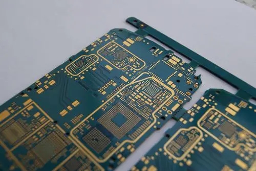
In the frequency band greater than 10GHz, PCB high-frequency circuit board microstrip printed antenna has obvious advantages over waveguide slot antenna, lens antenna, reflector antenna and other antennas. The mature processing technology of PCB high-frequency circuit board can effectively control the production cost of microstrip antenna. The multi-layer mixed voltage technology of high-frequency circuit board, antenna board, RF board and low-frequency digital analog circuit board also makes the entire RF system highly integrated. The RO4350B plate produced by Rogers Company has excellent high-frequency performance and low production cost, and has been widely used and verified in commercial RF systems. The author has successfully designed a series of 24 GHz microstrip array antennas using Rogers RO4350B high-frequency circuit board, which have been applied to the company's listed products. Therefore, some design skills of PCB high-frequency circuit board are summarized for their application.
Antenna type
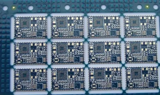
The microstrip array antenna is divided into parallel fed array and series fed array according to the feeding mode. The feeder line of parallel feed array is long, which leads to large incoming loss of feed network. For large arrays, the antenna efficiency is often limited, so the series fed array with more concise routing is generally selected. The series fed array is a resonant antenna, and its working bandwidth is SMAller than that of the parallel fed array, but the series fed structure is easier to realize the weighted excitation. RF boards adopt RO4350B boards with a thickness of 20mil. As the size of the array increases, the impedance bandwidth decreases gradually. The bandwidth is 1.2GHz with 16 elements, but only 0.75GHz with 324 elements. The frequency modulation bandwidth of the 24 GHz radar using the continuous wave system is usually less than 250 MHz, so the impedance bandwidth of the series fed array can meet the design requirements of most systems.
Thickness selection
The thickness selection is mainly based on three factors: the working bandwidth of the high-frequency circuit board microstrip antenna, the feed network design and the antenna efficiency.
1、 The thickness of the PCB high-frequency circuit board affects the impedance bandwidth of the microstrip antenna. The smaller the thickness of the PCB high-frequency circuit board, the larger the array size, the smaller the working bandwidth of the antenna.
2、 The thickness of the high frequency PCB circuit board determines the width of the microstrip line in the impedance change section of the feed network. For the RO4350B plate with a thickness of 20mil, the width of the 50 Ω and 100 Ω microstrip lines is 1.13mm and 0.27mm respectively, while the corresponding resonant length of the microstrip antenna at 24GHz is about 3mm. If the impedance of a microstrip change section in the feed network is too small or too large, the microstrip line will be too wide or too narrow. If the microstrip line is too wide, it is easy to cause structural interference, Narrow microstrip line will lead to processing difficulties.
3、 The dielectric thickness affects the conductor loss of microstrip line, and then affects the antenna efficiency. Based on the above factors, the author's RF board design experience is that small arrays should be 10 mil or 20 mil thick, large arrays should be 20 mil thick, and RF boards should be 10 mil thick. Of course, we can make whatever thickness you need.
Interconnection of antenna and RF chip
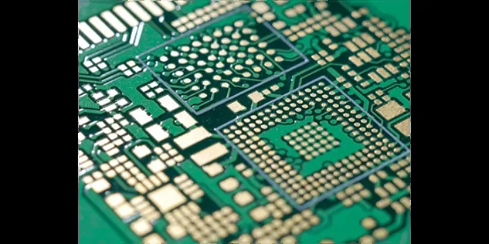
At present, doMEStic and foreign chip manufacturers have mass produced 24GHz RF chips on the MARKet. In the zero IF radar architecture, the pins of the RF chips are directly connected to the microstrip transceiver antenna ports. When the antenna board (HF board/HF circuit board)+several layers of common FR4+RF board (HF board/HF circuit board) HF board composite plates (such as FR4+RO4350b/FR4+RO3003/FR4+RO3006/FR4+RO5880) are used, the interconnection between the antenna and RF chip is realized through metallized vias. In the 24GHz frequency band, the discontinuity introduced by metallized vias longer than 1mm will be very obvious. The solution is to add several symmetrical metallized grounding vias around the metallized vias to form a coaxial like transmission structure. When the antenna and RF chip are located on the same side of the PCB high-frequency circuit board, the RF chip and the transceiver antenna are directly connected through the microstrip line or the coplanar waveguide. This high-frequency circuit board design can minimize the transmission line insertion loss. PCB manufacturers, PCB designers and PCBA manufacturers will explain the design skills of high-frequency PCB: 24 GHz microstrip array antenna.


抖音二維碼

Q Q二維碼

微信二維碼
點擊
然后
聯系
然后
聯系
電話熱線
13410863085Q Q

微信

- 郵箱