鑫景福致力于滿足“快速服務,零缺陷,輔助研發”PCBA訂購單需求。


PCBA方案設計

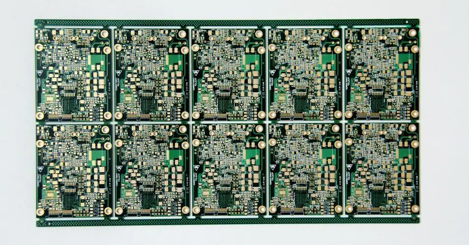
Factors affecting PCB welding quality
From PCB design to the completion of all components welding for a high quality circuit board, PCB design engineers and even the level of welding technology, welding workers and many other links have strICt control.
There are mainly the following factors: PCB diagram, the quality of the circuit board, the quality of the device, the oxidation degree of the device pin, the quality of the solder paste, the printing quality of the solder paste, the accuracy of the programming of the lamination machine, the quality of the lamination machine, the setting of the temperature curve of the reflow furnace and so on.
PCB drawing is the link that the welding plant itself cannot surmount. Because the people who do circuit design often do not solder circuit boards can not obtain direct welding experience, do not know the impact of various factors welding; The welding factory workers do not understand the drawing board, they only complete the production task, no mind, more do not have the ability to analyze the causes of bad welding. Because these two aspects of talent each perform their own duties, it is difficult to organically combine.

Suggestions for drawing PCB drawings
Below, I give some suggestions to PCB drawing design and wiring engineers, hoping to avoid all kinds of bad drawing methods that affect welding quality in the process of drawing.
About the positioning hole
Four holes (minimum aperture 2.5mm) should be left in the corners of the PCB board for positioning the circuit board when printing solder paste. The center of the X-axis or Y-axis is required to be on the same axis.
About the MARK point
Used for placement machine positioning. Mark mark on PCB board, specific position: on the diagonal of the board, can be round or square pads, do not mix with other device pads. If there are two-sided devices, both sides should be marked.
When designing PCB, please note the following points:
A. The shape of Mark point should be symmetrical up and down or left and right
The dimensions of b and A are 2.0mm.
c. There should be no shape or color changes within 2.0mm from the outer edge of the Mark point that could cause false recognition. (pad, solder paste)
D. The color of Mark should be different from the color of the surrounding PCB.
e. To ensure recognition accuracy, the surface of Mark spots is plated with copper or tin to prevent surface reflection. The shape is marked only by lines, not by points of light.
About leaving 5mm edge
When drawing PCB, at least 3mm edge should be left in the long side direction for the mounter to transport the circuit board. The mounter cannot mount devices in this range. Do not place patch devices within this range.
Double-sided circuit boards with devices should be considered the second reflux will have a welded side of the device to rub off, serious will rub off the pad, damage the circuit board.
Therefore, it is recommended not to place a patch device within 5mm of the long side of the SMAll side of the chip (generally the Bottom side). If the board area is really limited, you can add a process edge to the long side.
Do not drill directly into the pad
Directly on the pad hole defect is in the back flow after the solder paste melting into the hole, resulting in the device pad tin deficiency, thus forming virtual welding.
Polarity labeling of diode and tantalum capacitors
Polarity LABELS OF DIODE and tantalum capacitors should be in line with industry regulations to avoid welding in the wrong direction by workers' experience.
About screen printing and logos
Hide the device model. Especially the circuit board with high device density. Otherwise, the dazzling effect is to find the welding position. Don't just mark the model, not the label. The size of screen characters should not be too small to read clearly. Characters should be placed in staggered positions to avoid misreading.
The IC pads should be extended
When drawing PCB for IC encapsulated in SOP, PLCC and QFP, the solder pad should be extended. The length of solder pad on PCB =IC foot length ×1.5 is appropriate. In this way, chip pin, PCB solder pad and tin can be fused into one when manually welded with soldering iron.
About the width of IC pads
For IC encapsulated in SOP, PLCC, QFP, etc., the width of solder pad should be noted when drawing PCB. The width of solder pad a on PCB = the width of IC foot (Nom in datasheet). Value), please do not widen, ensure that b(i.e. between two pads) has sufficient width to avoid joint welding.
The thicker two devices should not be close together
The close cloth plate will cause the second device to be mounted by the laminator to touch the previous device, the machine will detect the danger, causing automatic power failure.
About the BGA
Because the BGA package is special, the solder pad is under the chip, and the welding effect can not be seen outside. For the convenience of repair, it is recommended to make two positioning holes with a Hole Size of 30mil on the PCB board, so as to locate the steel MESh (used for scraping solder paste) during repair.
Warm tip: the size of the positioning hole should not be too large or too small, to make the needle inserted after not dropping, not shaking, insert a little tight is appropriate, otherwise the positioning is not accurate.
And recommended BGA around a certain range to leave open space do not place devices, so that repair can be placed under the screen scraping paste.
About PCB board color
Do not make it red. Because the red circuit board is white under the red light source of the CAMera of the mounter, it cannot be programmed and is not convenient for the mounter to be welded.
About small devices under big devices
Some people like small devices in the same layer under the larger devices, such layout will cause difficulties to repair, repair must first remove the digital tube, and may cause damage to the digital tube. It is recommended that the resistance under the digital tube be drained to the Bottom side.
The connection between the copper-clad and the solder plate affects the melting tin
Due to the copper-clad will absorb a large amount of heat, resulting in the solder is difficult to fully melt, thus forming a virtual welding.
conclusion
Nowadays, there are more and more engineers who can draw, wire and design PCB with software. However, once the design is completed, the welding efficiency can be improved very well. The author believes that the above elements need to be paid attention to. And cultivate good drawing habits, to be able to communicate well with pcb processing plants, is every engineer should consider.


抖音二維碼

Q Q二維碼

微信二維碼
點擊
然后
聯系
然后
聯系
電話熱線
13410863085Q Q

微信

- 郵箱