鑫景福致力于滿足“快速服務,零缺陷,輔助研發”PCBA訂購單需求。


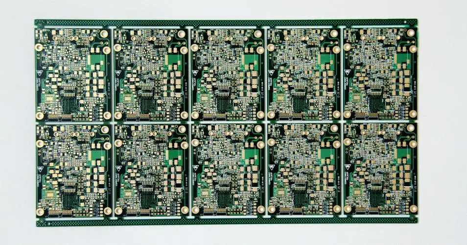
PCB制造
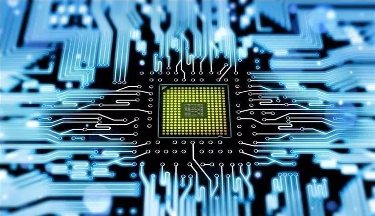
ElectronIC components and electromechanICal components all have electrical contacts, and the electrical connection between two discrete contacts is calLED interconnection. The electronic equipment must be interconnected according to the circuit board schematic diagram to achieve the intended function.
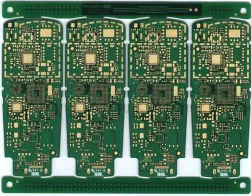
As an integral part of the whole machine, a PCB cannot generally constitute an electronic product, so there must be a problem of external connection. For example, electrical connection is required between printed boards, between printed boards and components outside the board, and between printed boards and equipment panels. It is one of the important contents of PCB design to select the connection with the best combination of reliability, process and economy. There are many external connection modes, which should be flexibly selected according to different characteristics.
Interconnection mode I of circuit board, welding mode
The connection mode has the advantages of SIMplicity, low cost, high reliability, and can avoid faults caused by poor contact; The disadvantage is that the exchange and maintenance are not convenient enough. This method is generally applicable to the case where the assembly has few external leads.
1. PCB wire welding
This method does not require any connectors, as long as the external connection points on the PCB are directly welded with the components or other components outside the board with wires. For example, the speaker and battery box in the radio.
Pay attention to:
(1) The bonding pads for welding wires shall be located at the edge of PCB printed board as far as possible and arranged in a uniform size to facilitate welding and maintenance.
(2) In order to improve the mechanical strength of wire connection and avoid pulling off the bonding pad or printed wire due to the pulling of the wire, drill holes near the solder joints on the PCB printed board, let the wire pass through the through hole from the PCB welding surface, and then insert the bonding pad hole from the PCB component surface for welding.
(3) The wires shall be arranged or bundled neatly, and fixed with the board by wire clips or other fasteners to prevent the wires from breaking due to movement.
2. PCB flat wire welding
The flat wire connection is adopted between the two PCB printed boards, which is reliable and not prone to connection errors, and the relative position of the two PCB printed boards is not limited.
Direct welding between printed boards is usually used for the connection of two printed boards with an included angle of 90 degrees. After connection, it becoMES an integral PCB printed board assembly.
Interconnection mode 2 of circuit board: connector connection mode
In more complex instruments and equipment, connector connection is often used. This "building block" structure not only ensures the quality of mass production, reduces the cost of the system, but also provides convenience for debugging and maintenance. When the equipment fails, the maintenance personnel do not need to check the PCB component level (that is, check the cause of the failure and trace it back to the specific component. This work takes a lot of time), as long as they judge which board is abnormal, they can immediately replace it, eliminate the failure in the shortest time, shorten the downtime, and improve the utilization of the equipment. The replaced circuit board can be repaired in sufficient time and used as a spare part after repair.
1. Printed board socket
This connection mode is often used in more complex instruments and equipment. This method is to make a printed plug from the edge of the PCB printed board. The plug part is designed according to the size of the socket, the number of connection points, the contact distance, the location of the positioning hole, etc., so that it can match with the special PCB printed board socket.
During plate making, the plug part needs to be gold-plated to improve wear resistance and reduce contact resistance. This method is simple in assembly, good in interchangeability and maintenance performance, and suitable for standardized mass production. Its disadvantage is that the cost of PCB is increased, and the requirements for manufacturing precision and process of PCB are high; The reliability is slightly poor, and the contact is often poor due to the oxidation of the plug part or the aging of the socket spring. In order to improve the reliability of external connection, the same outgoing line is often led out in parallel through the contacts on the same side or both sides of the circuit board.
PCB printed board socket connection mode is commonly used for products with multi board structure. There are two types of sockets: reed type and pin type.
2. Standard pin connection
This method can be used for external connection of printed boards, especially pin connection is often used in SMAll instruments. The two printed boards are connected by standard pins. The two printed boards are generally parallel or vertical, which is easy to achieve mass production.


抖音二維碼

Q Q二維碼

微信二維碼
點擊
然后
聯系
然后
聯系
電話熱線
13410863085Q Q

微信

- 郵箱