鑫景福致力于滿足“快速服務,零缺陷,輔助研發”PCBA訂購單需求。


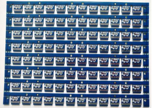
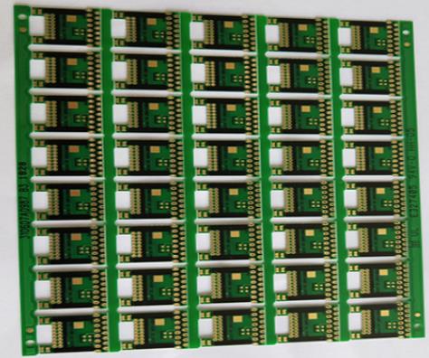
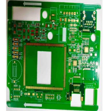
PCB制造
DielectrIC constant and material properties of high frequency plate
PCB manufacturers, PCB designers and PCBA processors will explain the dielectric constant of high-frequency boards (DK) and the basic characteristics of high-frequency board materials
The dielectric constant Dk of the high frequency board is one of the most important parameters of the printed circuit board. circuit designers rely on it to determine the impedance and physical size of the microstrip circuit. However, the dielectric constant Dk values of different high-frequency plates of the same material can often be seen in the laminate data, such as a process Dk and a specification Dk. Some materials will provide Dk values for CAD software. Why does the same parameter have so many values? Is there a high-frequency board Dk value that can be trusted in the design circuit.
In the manufacturing process of PCB, there are many different methods to measure the Dk value of microwave laminate, and different methods often give different results for the same material. Some measurement methods use the original PCB material that is not processed to form a circuit, while some methods use a circuit that can predict the familiar performance, so as to determine the dielectric constant Dk value of the material. The material manufacturer may use a statement SIMilar to the production dielectric constant Dk to specifically refer to the target value of the material in the production process. Generally, for a given laminate, the process Dk and specification Dk are the same.
A more meaningful Dk version is the design Dk published in Rogers' model selection manual, and it is also the Dk value used for MWI impedance calculator. This software can be obtained from Rogers' distributor Shiqiang in China. The design Dk value can provide the most accurate and repeatable results when used for circuit design purposes, especially in commercial CAE circuits and system simulation programs.
For some materials, the process or specification Dk may be the same as the design Dk. For example, the process Dk and design Dk of Rogers RT6002 microwave laminate are both 2.94 in the Z-axis direction. The only difference is that the process Dk in the sheet data is only for 10GHz, while the design Dk is applicable to the frequency range of 8GHz to 40GHz. Procedure Dk and design Dk are the results obtained by two different test methods.
At the same time, the Dk value of the high-frequency plate may be different. The process Dk of Rogers RO3010 laminate in 10GHzz axis is 10.2, but for the purpose of more accurate simulation, we recommend the design Dk of 11.2 when using commercial CAE software for simulation.
Since we have measured the value of process and specification Dk, why do we need a design Dk value? At present, there are many test methods to test Dk value of laminates. For example, the IPC of the Global Trade Organization lists 13 different test methods to determine the Dk value of materials. Material suppliers can use any of these test methods to determine their own high-frequency plate Dk values. Similarly, users of laminates may use their own different methods to determine the high-frequency plate Dk value of laminates before using it for design. For the two materials mentioned as examples before, each example uses different test methods to determine the process/specification Dk value and design Dk value: the clamping stripline method is used to determine the process/specification Dk value and the phase difference length method is used to measure the design Dk value.
For example, in Rogers, although the full plate resonance (FSR) test method can also be used for confirmatory testing, the X-band clamped stripline resonator test is used for the standard confirmatory testing of the specification or process high-frequency plate Dk. The separate dielectric resonator test (SPDR) method in Rogers can also be used to describe the characteristics of materials. In order to determine the design Dk value, all materials will be tested using the microstrip line differential phase length method.
Although no test method is perfect, the differential phase length method is popular because of its simplicity. It uses the same connector or test fixture to determine the phase difference between different circuits for a given test frequency based on the fact that two microstrip circuits with very different lengths are formed on the same laminate. Dk value can be determined by simple calculation according to physical length and phase difference. In the actual process, this process will be repeated as frequently as possible. This is not a fast method, but it does provide an accurate result in the z-axis direction, and heterogeneous materials (Dk values on the x-axis and y-axis) have little effect on the test.
This method is often used in practical microstrip circuits. In order to take the copper foil effect into account, this method is also applied to high-frequency testing. A piece of copper foil laminate with rough surface will have a higher Dk value of dominant high-frequency plate than that of copper foil laminate with smooth surface. The low frequency test method may not show the influence of copper foil surface roughness on the measured Dk value.
The design Dk of all high-frequency laminates of Rogers has been determined and reported to all CAE simulation software tool developers. In addition, these values have been included in MWI microwave impedance calculator, product selection guide and Rogers' calculation ruler.
Basic characteristics of high frequency plate materials
High frequency board is a special circuit board with high electromagnetic frequency. Generally speaking, high frequency can be defined as the frequency above 1GHz. Its physical performance, accuracy and technical parameters are very high, and are commonly used in automotive anti-collision systems, satellite systems, radio systems and other fields.
The basic characteristics of high-frequency plate materials are as follows:
1. Low water absorption and high water absorption will affect the dielectric constant and dielectric loss when affected with moisture.
2. The thermal expansion coefficient shall be consistent with that of copper foil as much as possible, because the inconsistency will cause copper foil separation in cold and hot changes.
3. The dielectric loss (Df) must be SMAll, which mainly affects the quality of signal transmission. The smaller the dielectric loss, the smaller the signal loss.
4. The dielectric constant (Dk) must be small and stable. In general, the smaller the better the signal transmission rate is, the inverse ratio of the square root of the dielectric constant of the material is. High dielectric constant is easy to cause signal transmission delay.
5. Other heat resistance, chEMIcal resistance, impact strength, peel strength, etc. must also be good.
PCB manufacturers, PCB designers and PCBA manufacturers will explain the dielectric constant of high-frequency boards (DK) and the basic characteristics of high-frequency board materials.


抖音二維碼

Q Q二維碼

微信二維碼
點擊
然后
聯系
然后
聯系
電話熱線
13410863085Q Q

微信

- 郵箱