鑫景福致力于滿足“快速服務(wù),零缺陷,輔助研發(fā)”PCBA訂購單需求。


行業(yè)新聞
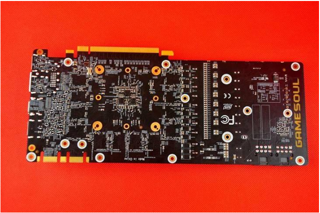
PCB sensing diagram of wearable wrist electronIC sphygmomanometer
Blood pressure meter PCB board
Circuit principle: BP01 pressure sensor and operational amplifier ($1.6646) are used in this circuit. BP01 type pressure sensor is specialized for detecting blood pressure, mainly used for portable electronic sphygmomanometer. It uses precision thick film ceramIC chips and nylon plastic packaging, with the characteristics of high linearity, low noise and low external stress; The internal calibration and temperature compensation methods are adopted to improve the measurement accuracy, stability and repeatability. Within the full range, the accuracy is ± 1% and the zero offset is not more than ± 300 μ V。 MAX4472 is a low-power amplification PCB chip integrated with four operational amplifiers from MAXIM. In this system, the internal integrated operational amplifier A is connected to a constant current source to provide a constant current for the pressure sensor. Operational amplifier B, operational amplifier C, and operational amplifier D form a differential input, single ended outpu
tamplifier circuit that directly inputs ADC0 to monitor the DC component of blood pressure.
BP01 pressure sensor is specially designed for monitoring blood pressure, and is mainly used for portable electronic sphygmomanometer. It uses precision thick film ceramic chips and nylon plastic packaging, with the characteristics of high linearity, low noise and low external stress; The internal calibration and temperature compensation methods are adopted to improve the measurement accuracy, stability and repeatability. Within the full range, the accuracy is ± 1%, and the zero offset is not more than ± 300 μ V。
Working principle: The principle circuit of the portable electronic sphygmomanometer composed of BP01 is composed of bias power supply circuit (A1, A2), pre-processing circuit (A3~A6), display circuit (A7) and pressure sensor (BP01). The blood pressure measurement range of the sphygmomanometer is 0~200mmHg, the resolution is 0.1mmHg, and the working power supply is a 9V laminated battery. The working principle of each main circuit in the sphygmomanometer is described as follows:
Bias power supply circuit: the power supply circuit is composed of a dual operational amplifier LM10 with a built-in reference PCB voltage. A1 forms an in-phase amplifier, and A2 forms a follower. Their role is to amplify the built-in reference voltage and use it as the bias voltage Vs of the pressure sensor BP01. The value of Vs is determined by the following formula: Vs=Vref (1+R2/R3) Where, Vref is the built-in reference voltage of LM10. Its value is 200mV. Substitute this value together with the R2 and R3 values in the circuit into the above equation to obtain the value of bias voltage Vs as 5V.
Pre processing circuit: the pre processing circuit is composed of four operational amplifiers A3~A6, wherein A3 constitutes an offset bias circuit to compensate for circuit offset; A5 constitutes a follower for isolating and buffering the output signal of pressure sensor BP01; A4 and A6 form an amplifier circuit, whose gain AV is determined by the following formula: AV=1+(R1/RT) If the offset is ignored, the output voltage Vout of the pre-processing circuit is Vout=2 (1+R1/RT) VIN where VIN is the output voltage of the pressure sensor BP01.
Display circuit: the display circuit uses a three and a half digit display driver. During operation, the output of pressure sensor BP01 is amplified by the pre-processing circuit, and the LCD is driven by the display drive circuit to read the measured blood pressure value.
Debugging method: When the zero pressure output is adjusted, adjust the imbalance potentiometer RP1. When the display value of the sphygmomanometer is 000.0, the zero pressure output adjustment is considered completed.
Electronic auxiliary sphygmomanometer
These two kinds of sphygmomanometers (blood pressure gauges) account for more than 90% of the current social ownership, and are the main tools for doctors to measure blood pressure for patients. Family ownership is also large. However, this kind of sphygmomanometer needs stethoscope to assist in measuring blood pressure, and must have certain measurement technology, especially for the judgment of diastolic blood pressure (commonly known as low pressure), which has large human error factors. This paper introduces an electronic auxiliary measuring device for PCB enthusiasts. The auxiliary measuring device can make the blood pressure measurement more accurate and convenient. It not only replaces the stethoscope, but also can observe the measured blood pressure value at the same time, so that people who do not know the measuring skills can also measure the blood pressure accurately.
Working principle of PCB:
The measuring device is composed of acoustic wave acquisition, voltage amplification, low-pass filtering, waveform transformation, voltage detection and acousto-optic display circuit.
HTD1 sends the detected pulse beating acoustic signal to the grid of V1, where V1 plays the role of impedance transformation. It converts the weak acoustic signal voltage with high internal resistance into a low impedance output, and then couples it to IC1 through C1, C2, C4. IC1 is a four op amp. The internal circuit of pins ⑤, ⑥, and ⑦ and the peripheral PCB components constitute a voltage amplifier. Changing the resistance value of R8 can adjust the magnification of this level. The amplified audio signal is coupLED to a low-pass filter composed of internal and external circuits of ①, ② and ③ pins through R9 and C6 to eliminate human body induction and external interference signals. And improve the load carrying capacity. The signal is output from pin ① and coupled to pins 12, 13 and 14 through C8 for shaping and amplification. The pulse acoustic wave is converted into a square wave and output from pin 14. Adjusting w1 can change the amplification. The square wave signal output from pin 14 is directly coupled to pin ③ and pin 12 of IC2. After being amplified by two operational amplifiers, it is output by pin ① and pin 14 respectively. The square wave voltage output from pin ① is coupled to pin 12 and pin 13 of IC3 through D6. IC3 is a four NAND gate circuit. When pins 12 and 13 are high level, pin ② outputs low-level D7 luminous indication. Adjust the capacity of C12 to change D7 luminous delay time. The high level square wave pulse output from pin 14 of IC2 is coupled to pin ① of IC3 through D5, and the internal and external circuits of pins ①, ②, ③, ④, ⑤, ⑥ form an oscillator. ① The foot is a high level oscillator, which starts to vibrate and makes a sound. Its oscillation frequency is about 2000Hz. The ⑤ - ⑩ pin circuits of V2 and IC2 play the role of acousto-optic synchronization.
The ⑧, ⑨ and ⑩ pin circuits of IC1 form a voltage detector to prevent loss of measurement accuracy when the battery voltage is too low. D1 provides 4.5V reference voltage for ⑩ pin, and R17, W2 and R18 form a voltage divider. Adjust W2 to set the start control voltage value. When the voltage of pin ⑨ is lower than that of pin ⑩, pin ⑧ outputs high level and D2 EMIts light, indicating that the PCB voltage is too low and the battery should be replaced. The auxiliary measuring device consuMES very little power, and can be used for more than one year if the battery is replaced once.


抖音二維碼

Q Q二維碼

微信二維碼
點(diǎn)擊
然后
聯(lián)系
然后
聯(lián)系
電話熱線
13410863085Q Q

微信

- 郵箱