鑫景福致力于滿足“快速服務(wù),零缺陷,輔助研發(fā)”PCBA訂購(gòu)單需求。


PCBA方案設(shè)計(jì)
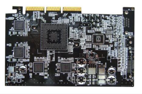
design for manufacturability of through hole PCB 2
If the PCB design does not meet the requirements of manufacturability design, it will greatly reduce the production effICiency of products In some cases, the designed products cannot be manufactured At present, through hole insertion technology (THT for short) is still in use DFM can play an important role in improving the efficiency and reliability of through-hole insertion manufacturing DFM method can help through hole insertion manufacturers reduce defects Keep competitive
1 Typesetting and layout
(1) Using a large board can save materials, but due to warpage and weight, it is difficult to transport them during production So try to avoid using a board surface larger than 2.3 cm * 30 cm Control the size of all circuit boards within two to three, which will help reduce the downtime caused by rail adjustment, rearrange the position of barcode readers, etc When the product is replaced, SMAll changes in the size of the circuit board can also reduce the number of peaks in the welding temperature curve
(2) It is a good design method to include different kinds of panels in one board Please do not copy the content of this site

(3) Some borders should be provided around the board, especially when there are components on the edge of the circuit board, most automatic assembly equipment requires that the edge of the circuit board have at least a 5 mm area
(4.) Make wiring on the top surface (component surface) of the board as much as possible, and the bottom surface (soldering surface) of the circuit board is easily damaged. Do not wire near the edge of the circuit board, because the production process is caught by the edge of the circuit board, and the jaw of the wave soldering equipment or the frame conveyor may damage the wiring on the edge
(5) For devices with higher pin counts (such as terminal blocks or flat cables), oval pads should be used instead of round pads to prevent welding bridges during wave soldering
(6) Make the spacing between the positioning holes and the distance between them and the components as large as possible; Do not plate the positioning hole, because the diameter of the plated hole is difficult to control
(7) Try to use the positioning hole as the mounting hole of the PCB board
(8) A test circuit pattern can be arranged on the waste side of the board for process control During the manufacturing process
(9) For larger boards, during wave soldering, a channel shall be left in the center to support the circuit board in the center, prevent the circuit board from sagging and solder splashing, and help the board surface to weld in a consistent manner
(10) The testability of the needle bed should be considered in the layout design. Flat pads (without leads) can be used for better connection with the pins during online testing
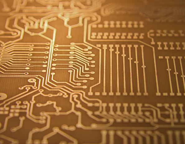
printed circuit board
2. Positioning and placement of components
(1) Arrange components in rows and columns according to a grid pattern position
(2) SIMilar elements shall be discharged in the same way on the board. For example, make the negative pole of all radial capacitors face the right side of the circuit board, make all tilt notch MARKs face the same direction, etc, This speeds up insertion and makes it easier to find errors Because board A adopts this method, the reverse capacitor is easy to find, while board B needs more time to search In fact, the company can standardize the direction of all circuit board components it manufactures. Some circuit board layouts may not necessarily allow this, but this should be an effort
(3) The arrangement direction of dual in line package devices, connectors and other multi pin counting elements are perpendicular to the wave soldering direction, which can reduce the tin bridge between element pins
(4) Make full use of silver screen printing to mark the board surface, for example, draw a frame for pasting bar codes, print arrows to instruct the peak welding direction of the board, and use dotted lines to trace the outline of the components on the bottom surface (so that the board only needs to be screen printed), etc
(5) Draw the component reference character (CRD) and polarity indication, and the component is still visible after being inserted. This is very helpful in checking and troubleshooting, and is also a good maintenance work
(6) The distance between the components and the edge of the board should be at least 1.5 mm (3 mm), which will make the circuit board easier to transfer and wave soldering, and The damage to peripheral components will be less
(7) When the distance of the components above the board surface needs to exceed 2mm (such as light EMItting diodes, high-power resistors, etc.), add shims below it Without gasket, these elements will be "squeezed" during transportation and are vulnerable to impact during use
(8) Avoid laying components on both sides of the PCB, because this will greatly increase the labor and time for assembly If the components must be placed underneath, they should be physically tight together to mask and peel off the solder mask tape
(9) Try to distribute the components even on the PCB to reduce warpage and help distribute heat evenly during wave soldering
3. Machine insertion
(1) The pads for all components on the board should be standard and industry standard separation distances should be used.
(2) The selected components should be suitable for machine insertion. Please remember the equipment conditions and specifications of your own factory, and consider the packaging form of components in advance, so as to better cooperate with the machine Packaging may be a bigger problem for odd shaped components
(3) If possible, use axial and radial components as much as possible, because the insertion cost of axial components is relatively low. If space is very valuable, radial components can also be preferred
(4) If there are only a small number of axial elements on the board
(5) When arranging the board surface, the bending direction of the pin and the range reached by the automatic insertion machine components should be considered from the perspective of power spacing, and at the same time, it should be ensured that the bending direction of the pin will not lead to a tin bridge
4. Wires and connectors
(1) Do not connect wires or cables directly to the PCB, but use connectors If the wire must be directly welded to the circuit board, the end of the wire shall be terminated to the terminal of the circuit board with a wire Wires from the circuit board shall be concentrated in a certain area of the circuit board, so that they can be nested together to avoid affecting other components
(2) Use wires of different colors to prevent errors during assembly. Each company can use its own color scheme. For example, blue represents the high position of all product data lines, and yellow represents the low position
(3) Connectors should have larger pads to provide better mechanical connection
(4) Avoid the use of dual-in-line package sockets. In addition to extending assembly time, this additional mechanical connection also reduces long-term reliability Use the socket only when the DIP field needs to be replaced for maintenance reasons The quality of DIP has made great progress, and it does not need to be replaced frequently
(5) Marks for identifying the direction should be engraved on the board to prevent errors when installing the connector. Connector solder joints are places where mechanical stress is concentrated. It is recommended to use some clamping tools, such as keyfraMES and snapshots
The above is the explanation given by the editor of pcb circuit board company.
If you want to know more about PCBA, you can go to our company's home page to learn about it.
In addition, our company also sells various circuit boards,
High Frequency Circuit Board and SMT chip are waiting for your presence again.


抖音二維碼

Q Q二維碼

微信二維碼
點(diǎn)擊
然后
聯(lián)系
然后
聯(lián)系
電話熱線
13410863085Q Q

微信

- 郵箱