鑫景福致力于滿足“快速服務,零缺陷,輔助研發”PCBA訂購單需求。


PCBA方案設計
How to place RF circuit and digital circuit on PCB
They can be integrated in a small PCB for wireless digital audio, digital video data transmission systems, wireless remote control and telemetry systems, wireless data acquisition systems, wireless networks and wireless security systems, and many other fields The monolithIC RF device is greatly convenient, and the following methods can be used to form a complete wireless communication connection:
1 Potential conflicts between digital circuits and analog circuits
If the analytical circuit (RF) and the digital circuit (microcontroller) work separately, they may work well, but once they are placed on the same board and powered by the same power supply, the whole system may be unstable. This is mainly because the digital signal frequently swings between the ground and the positive power supply (3. V in size), and the cycle is very short, usually at the ns level Because of the large amplitude and SMAll switching time, these digital signals contain a large number of high-frequency components independent of switching frequency In the analog part, the signal transmitted from the antenna tuning loop to the wireless device receiving part is usually less than 1mV So the difference between the digital signal and the RF signal will be 10-6 (12.0 dB). Obviously, if the digital signal is not well separated from the RF signal, the weak RF signal may be damaged. In retrOSPect, the working efficiency of the wireless device will deteriorate, or even be unable to work at all
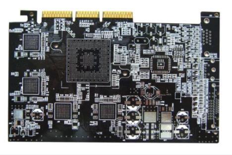
PCB board

2. Common problems with RF circuits and digital circuits on the same PCB
Insufficient isolation of sensitive and noisy signal lines is a common problem. As mentioned above, digital signals have high swing and contain a large number of high-frequency harmonics If digital signal wiring on PCB is adjacent to sensitive analog signal, high-frequency harmonic may pass through Sensitive nodes of RF devices are usually the phase locked loop (PLL) loop filter circuit, external voltage controlLED oscillator (VCO) instruction, crystal reference signals and antenna terminals. These parts of the circuit should be handled with special care
(1) Power supply noise
Since the input/output signal has a swing of several volts, digital circuits are generally acceptable for power supply noise (less than 50 mV) On the other hand, analog circuits are very sensitive to power supply noise, especially fault voltage and other high-frequency harmonics Therefore, the routing of power lines on PCB containing RF (or other analog) circuits must be done more carefully than on ordinal digital boards It should also be noted that a microcontroller (or other digital circuit) will gradually draw most of the current for a short period of time during each internal clock cycle Therefore, it will draw (pulse) current from the power supply at this frequency If these voltage faults reach the power supply pin of the RF part of the circuit, it may seriously lead to work failure. In this case, it is necessary to ensure that the analog power line is separated from the digital circuit
(2) Unreasonable ground wire
RF circuit boards should always have a ground plane connected to the negative side of the power supply This may be difficult for digital circuit designers to understand, because most digital circuits can work normally even without a ground plane In the RF band, even short wires can act as inductors Roughly calculated, the inductance per mm of length is about 1 nH, and the inductance of 10 mm PCB circuit at 434 MHz is about 27 Ω) Without a ground plane, most grounding wires will be long and the circuit will not guarantee the design characteristics
(3) Radiation from the antenna to other analog parts
In circuits containing RF and other parts, this is often ignored In addition to the RF part, there are usually other analog circuits on the board For example, many microcontrollers have built in analytical to digital converters (ADCs) for measuring analytical inputs as well as battery voltage or other parameters If the RF transmitter's antenna is located near (or on) this PCB, the transmitted high-frequency signal may reach the analog input of ADC Don't forget that any circuit line can send or receive RF signals like an antenna If the ADC input is not handled correctly, the RF signal may self excite in the ESD diode of the ADC input, causing the ADC to drift
3. Solution A with RF circuit and digital circuit on the same PCB
Some general design and routing strategies in most RF applications are given below. However, in practical applications, it is more important to follow the routing recommendations of RF devices
(1) A reliable ground plane
When designing a PCB with RF components, always use a reliable ground plane Its purpose is to establish an effective 0 V potential point in the circuit, allowing easy decoupling of all equipment The 0 V terminal of the power supply should be directly connected to this ground plane Due to the low impedance of the ground plane, there will be no signal coupling between the decoupled two nodes This is important because the amplitudes of multiple signals on the circuit board may differ by 120 dB On the surface mounted PCB, all signals are routed on the same side of the component mounting surface, and the ground plane is on the other side The ideal ground plane should cover the entire PCB (except under the antenna PCB). If more than two PCBs are used, the ground layer should be placed on the layer adjacent to the signal layer (such as the next layer on the component side) Another good method is to fill the blank part of the signal routing layer with the ground plane, which must be connected to the main ground plane through multiple vias It should be noted that the existence of the grounding point will lead to changes in the inductance characteristics beside it. The selection of inductance value and the arrangement of inductance must be carefully considered
(2) Shorten the connection distance to the ground layer
All connections to ground planes must be kept as short as possible, and ground vias should be placed at (or very close to) the component pads. Two grounding signals are not allowed to pass through. Because of the through hole connection impedance, this may cause crosstalk between two pads
(3) RF decoupling
Decoupling capacitors should be placed as close to the pins as possible High quality ceramic capacitors are used. The dielectric type is "NPO". "X7R" is also suitable for most applications The ideal capacitance value should be selected so that its series resonance is equal to the signal frequency For example, a 100 pF capacitor installed on the SMD will work well at 434 MHz At this frequency, the capacitive reactance of the capacitor is about 4 ? ?, Inductive reactance of through-hole is within the same range Capacitors and vias are connected in series to form a notch filter of signal frequency to achieve effective decoupling 33 pF capacitors are ideal for 868 MHz In addition to the small value capacitor used for RF decoupling, a large value capacitor should also be placed on the power line to decouple the low frequency Select a 2.2mF ceramic or 10mF tantalum capacitor
The above is the explanation given by the editor of pcb circuit board company.
If you want to know more about PCBA, you can go to our company's home page to learn about it.
In addition, our company also sells various circuit boards,
High Frequency Circuit Board and SMT chip are waiting for your presence again.

How to Design PCB Board with Irregular Shape
11-09,2022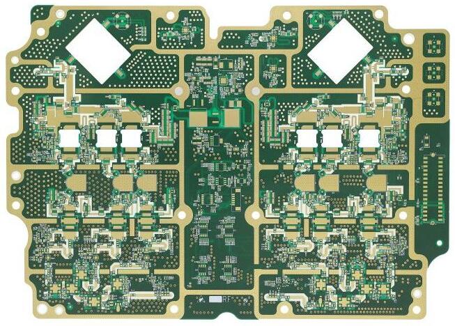


抖音二維碼

Q Q二維碼

微信二維碼
點擊
然后
聯系
然后
聯系
電話熱線
13410863085Q Q

微信

- 郵箱