鑫景福致力于滿足“快速服務,零缺陷,輔助研發”PCBA訂購單需求。


PCBA方案設計
How to design PCB Board with Irregular Shape
A complete PCB is usually a regular rectangle Although most designs are rectangular, it is a fact that many irregular shaped plates are often diffICult to design This paper introduces how to design irregular shaped PCB boards The size of today's PCB is shrinking. There are more and more functions in the PCB. Which one, with the increase of clock speed, makes the design more complex So let's look at how to deal with more complex shaped circuit boards However, when the shape coefficient of the circuit board needs to adapt to the complex enclosure with high constraints, the functions of these tools are different from those of mechanical CAD systems for those PCB boards complex circuit boards are mainly used for explosion-proof enclosures, which are subject to many mechanical limitations Attempting to reconstruct this information in EDA tools may take a long time and is inefficient Because it is likely that the mechanical engineer created the housing, the shape coefficient of the circuit board, the position of the mounting hole, and the height constraint PCB designer needs These are just a few examples of complex board profiles However, from today's consumer electronics, you will be surprised how many engineers try to package all the functions into a SMAll package of software that is not always rectangular You should consider smartphones and tablets, but there are many SIMilar examples If you return the car, you may see the attendant read the car information with a handheld scanner, and then communicate with the office wirelessly The device is also connected to a thermal printer for instant receipt printing In fact, all these devices use rigid/flexible circuit boards, where traditional PCB boards are interconnected with Flexible printed circuits, which can be folded into small spaces This question, then, Yes "How to import the defined mechanical engineering specifications into PCB design tools? "Reusing these data in mechanical drawings can eliminate duplication of labor and, more importantly, human errors. We can use DXF layout software, Israel Defense Forces or ProSTEP format by importing all information to PCB boards. This can save a lot of time and eliminate possible human errors. Next, we will look at these formats one by one
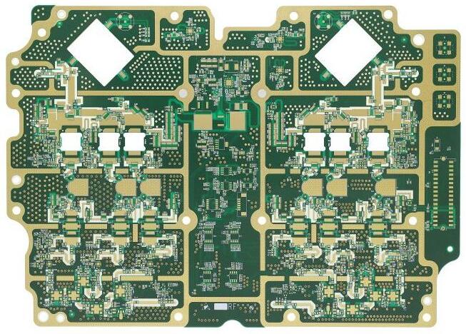
PCB board

Graphics Interchange Format - DXF
DXF is a long-established and widely used format for exchanging data between the mechanical and PCB design domains primarily electronically. AutoCAD developed it in the early 1980s This format is mainly used for two-dimensional data exchange Most PCB tool suppliers support this format, which really simplifies data exchange DXF import/export requires additional functions to control layers, different entities and elements to be used in the exchange process Figure 5 is an example of using Mentor Graphics' PADS tool to import very complex PCB shapes in DXF format a few years ago. 3D functions began to appear in PCB tools. I need a way to bridge the gap between machinery and machinePCB tools Format for transferring 3D data From this point, Mentor Graphics developed the IDF format. Since then, it has been widely used to transfer circuit boards and component information between PCB boards and machine tools The DXF format includes the size and thickness of the circuit board. The IDF format uses the X and Y positions of the component, the tag number of the component, and the Z-axis height of the component This format greatly changes the ability of visualization in 3D view of PCB Other information about forbidden areas may also be included in the IDF file, such as height limits at the top and bottom of the board The system needs to be able to control the content contained in the IDF file with a pipeline similar to the DXF parameter settings If some components do not have height information, IDF export can add missing information during creation
Another advantage of the IDF interface is that either party can move components to a new location or change the shape of the circuit board, and then create different IDF files The disadvantage of this method is that it needs to re import the entire file representing changes to the circuit board and components. In some cases, due to the file size, it may take a long time Moreover, it is difficult to determine what changes have been made to the new IDF file, especially on larger circuit boards IDF users can eventually create custom scripts to determine these changes
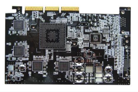
PCB board
STEP and ProSTEP
In order to better transmit 3D data, designers are looking for an improved method, and STEP format coMES into being STEP format can convey board size and component placement, but more importantly, components are no longer simple shapes with only height values STEP component model provides detaiLED and complex representation of 3D components pCB and component information can be transmitted between PCB and machine However, there is still no mechanism to track changes To improve STEP file exchange, we introduced ProSTEP format This format moves the same data as IDF and STEP, which has been greatly improved. It can track changes, provide the ability to work in the original system of the discipline, and review any changes after establishing a baseline In addition to reviewing the changes, the PCB mechanical engineer can approve all or single component changes in the layout, and modify the PCB outline They can also suggest different board sizes or component placement This improved communication creates an ECO (Engineering Change Order) between ECAD and the mechanical group that never existed before. Most ECAD and mechanical CAD systems now support the use of ProSTEP format to improve communication, save a lot of time, and reduce costly errors that may be caused by complex electromechanical design In addition, engineers can save time by creating complex circuit board profiles with additional constraints, and then passing this information through electronic channels to avoid people misinterpreting the circuit board size incorrectly
Summarize
If you have not used these DXF, IDF, STEP or ProSTEP data formats to exchange information, you should check their usage Consider using this electronic data exchange to stop wasting time recreating complex PCB board profiles
The above is the explanation given by the editor of pcb circuit board company.
If you want to know more about PCBA, you can go to our company's home page to learn about it.
In addition, our company also sells various circuit boards,
High Frequency Circuit Board and SMT chip are waiting for your presence again.


抖音二維碼

Q Q二維碼

微信二維碼
點擊
然后
聯系
然后
聯系
電話熱線
13410863085Q Q

微信

- 郵箱