鑫景福致力于滿足“快速服務(wù),零缺陷,輔助研發(fā)”PCBA訂購單需求。


PCBA方案設(shè)計
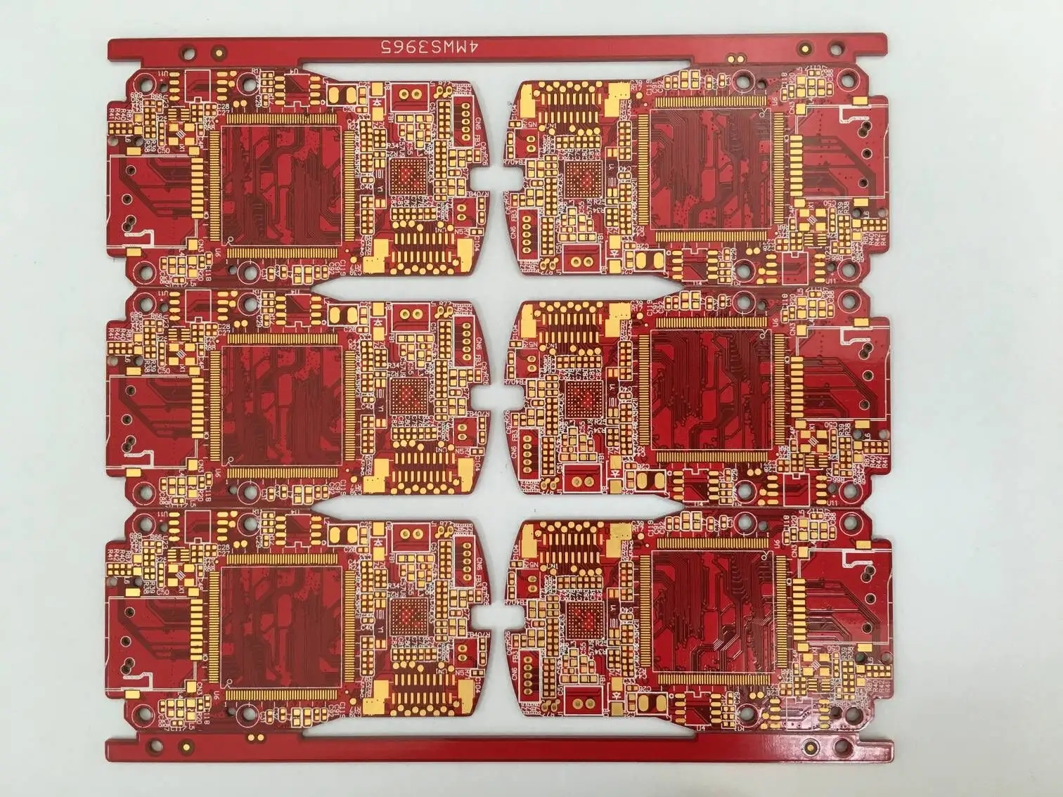
The knowLEDge of circuit board that high frequency pcb board must master
circuit board manufacturing, circuit board design and PCBA processing manufacturers will explain the circuit board knowledge that you must master for high-frequency PCB boards
If the circuit system designed by the high-frequency pcb board contains FPGA devICes, you must use QuartusII software to verify the pin assignment before drawing the schematic diagram. (Some special pins in FPGA cannot be used as ordinary IO).
2. The four layers of hf PCB board/hf board/hf microwave RF board from top to bottom are: signal plane layer, ground, power supply, signal plane layer; 6-layer board (high-frequency PCB board) from top to bottom is: signal plane layer, ground, signal inner electric layer, signal inner electric layer, power supply, signal plane layer. For boards above 6 layers (the advantage is: interference radiation prevention), the internal power layer is preferred for wiring, and the plane layer is not available for wiring, and wiring from the ground or power layer is prohibited (reason: the power layer will be divided, resulting in parasitic effects).
3. Wiring of multi power supply system: For example, FPGA+DSP System is made of six layers of boards (high-frequency PCB board/high-frequency board/high-frequency microwave RF board), which generally has at least 3.3V+1.2V+1.8V+5V.
① 3V is generally the main power supply, which is directly laid on the power layer. It is easy to lay the global power network through the vias;
5V may be power input generally, and only a SMAll area needs to be paved with copper. And try to be as thick as possible.
② 2V and 1.8V are core power supplies (it will be very difficult to face BGA devices if wiring is used directly). In the layout, try to separate 1.2V from 1.8V, and let the components connected within 1.2V or 1.8V be arranged in a compact area and connected by copper sheet.
In a word, because the power network is distributed throughout the high-frequency pcb board, if the wiring method is used, it will be very complicated and far away. The copper coating method is a good choice!
4. Crossing mode is adopted for routing between adjacent layers: it can not only reduce electromagnetic interference between parallel conductors, but also facilitate routing.
5. How to isolate analog and digital? During layout, separate the devices used for analog signals from those used for digital signals, and then cut across the middle of AD chips!
The analog signal is laid on the analog ground, and the analog ground/analog power supply and digital power supply are connected through a single point of inductance/magnetic bead.
6. The design of high frequency pcb board based on the design software of high frequency PCB board/high frequency board/high frequency microwave rf board can also be regarded as a software development process. Software engineering pays most attention to the idea of "iterative development" to reduce the probability of error of high frequency pcb board.
① High frequency pcb board packaging drawing (confirm whether the pins in the schematic diagram are wrong);;
② After confirming the package sizes of high-frequency PCB boards one by one, add verification labels to the package library of this design;
③ Check the schematic diagram, especially pay attention to the power supply and ground of the device (the power supply and ground are the blood of the system, and no negligence is allowed);
④ Manual wiring (check the power supply and ground network while laying. As mentioned earlier, the power supply network uses copper laying, so less wiring is used);
⑤ Import the net list, and adjust the signal sequence in the schematic diagram while layout (after layout, the automatic numbering function of OrCAD components can no longer be used);
In a word, the guiding ideology in the design of high-frequency pcb board is to feed back and correct the schematic diagram while drawing the package layout (considering the correctness of signal connection and the convenience of signal routing).
7. The crystal oscillator shall be as close to the chip as possible, and the wiring under the crystal oscillator shall be avoided as much as possible, and the network copper skin shall be paved. The clock used in many places is wired in a tree clock tree mode.
8. The arrangement of the signal on the connector has a great impact on the difficulty of wiring, so it is necessary to adjust the signal on the schematic diagram while wiring (but never re number the components).
9. Multi board connector design:
① Straight socket: upper and lower interfaces are mirrored symmetrically;
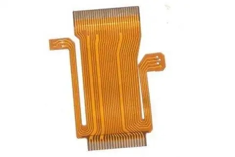
② Use flat cable connection: the upper and lower interfaces are consistent.
10. Design of module connection signal:
① If the two modules are placed on different sides of the high-frequency pcb board, the discipline serial number is small to large;
② If the two modules are placed on the same side of the high-frequency pcb board, the discipline serial number is larger than the small one (mirror connection signal).
In this way, signals can be placed to cross as shown in the right figure above. Of course, the above method is not a rule. I always say that everything changes as needed (this can only be understood by yourself), but in many cases it is very useful to design in this way.
11. Design of power and ground circuit:
The power supply and ground wire are close to the wiring, reducing the loop area and electromagnetic interference (679/12.8, about 54 tiMES). Therefore, the power supply and ground should be as close to the wiring as possible! The parallel routing between signal lines should be avoided as far as possible to reduce mutual inductance between signals. PCB manufacturers, PCB designers and PCBA manufacturers will explain the PCB knowledge that you must master for high-frequency PCB boards.


抖音二維碼

Q Q二維碼

微信二維碼
點擊
然后
聯(lián)系
然后
聯(lián)系
電話熱線
13410863085Q Q

微信

- 郵箱