鑫景福致力于滿足“快速服務,零缺陷,輔助研發”PCBA訂購單需求。


PCBA方案設計
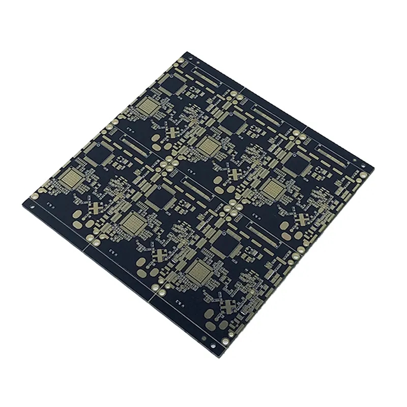
circuit board and circuit anti-interference power line design and ground wire design
The circuit board manufacturer, circuit board designer and PCBA manufacturer will explain the circuit board and circuit anti-interference power cord design and ground wire design
The anti-interference design of printed circuit board is closely related to the specifIC circuit. The following four aspects discuss the anti-interference design measures of PCB.
1. Power cord design
According to the current of the printed circuit board, the width of the power line shall be thickened as much as possible to reduce the loop resistance. At the same time, the direction of power line and ground wire is consistent with the direction of data transmission, which helps to enhance the anti noise ability.
2. Ground wire design
On the printed circuit board, the power cord and ground wire are the most important. The most important way to overcome electromagnetic interference is grounding. For double-sided boards, the ground wire layout is particularly particular. By using the single point grounding method, the power and ground are connected to the printed circuit board from both ends of the power supply, with one contact for the power supply and one contact for the ground. On the printed circuit board, there should be multiple return ground wires, which will converge to the contact of the return power supply, which is calLED single point grounding. The so-called opening of analog ground, digital ground and high-power devices means that the wiring is separated and finally gathered to this grounding point. Shielded cables are usually used to connect signals outside the printed circuit board. For high frequency and digital signals, both ends of the shielded cable are grounded. One end of the shielded cable used for low-frequency analog signal should be grounded. If the grounding and shielding can be correctly combined, most interference problems can be solved. Ground wire structures in electronic equipment generally include system ground, enclosure ground (shielding ground), digital ground (logic ground) and analog ground. The principle of ground wire design is:

Separated digitally from analog. If there are both logic circuits and linear circuits on the circuit board, they should be separated as much as possible, connected to the ground wire at the power supply end respectively, and the grounding area of the linear circuit should be increased as much as possible. The grounding of low-frequency circuit shall adopt single point parallel grounding as far as possible. If the actual wiring is difficult, part of the circuit can be connected in series and then connected to the ground in parallel. High frequency circuit should adopt multipoint series grounding, the ground wire should be short and thick, and grid shaped large area ground foil should be used around high-frequency components as far as possible.
The grounding wire shall be thickened as much as possible. If the grounding wire is very thin, the grounding potential will change with the change of current, resulting in unstable timing signal level of electronic equipment and poor anti noise performance. Therefore, the grounding wire should be thickened so that it can pass three tiMES the allowable current on the printed board. If possible, the width of grounding wire shall be more than 2-3 mm.
Correctly select single point grounding and multi-point grounding. In the low-frequency circuit, the working frequency of the signal is less than 1MHz, its wiring and inductance between components have less influence, while the circulating current formed by the grounding circuit has greater influence on the interference, so one point grounding should be adopted. When the signal operating frequency is greater than 10MHz, the ground wire impedance becomes large. At this time, the ground wire impedance should be reduced as much as possible, and the nearest multipoint grounding should be adopted. When the working frequency is 1~10MHz, if one point grounding is adopted, the length of the ground wire shall not exceed 1/20 of the wavelength, otherwise the multi-point grounding method shall be adopted.
Make the grounding wire into a closed loop. When designing the ground wire system of printed circuit board composed of digital circuits only, making the ground wire into a closed loop can obviously improve the anti noise ability. The reason is that many integrated circuit components on the printed circuit board, especially those with high power consumption, will produce large potential difference on the ground junction due to the limitation of the thickness of the grounding wire, resulting in a decline in anti noise capability. If the grounding is formed into a loop, the potential difference will be reduced and the anti noise capability of electronic equipment will be improved. The Circuit board manufacturer, circuit board designer and PCBA manufacturer will explain the circuit board and circuit anti-interference power cord design and ground wire design.


抖音二維碼

Q Q二維碼

微信二維碼
點擊
然后
聯系
然后
聯系
電話熱線
13410863085Q Q

微信

- 郵箱